
Use of Beam Scanning to Improve Uniformity and Productivity of a 2D Mechanical Scan Implantation System

a mechanical scan and beam scanning technology, applied in the field of ion implantation systems, can solve the problems of reducing the number of scan lines across the wafer, the inability of the two-dimensional scanning system to achieve the same scanning speed as the batch tools, and the micro-uniformity of the dose across, so as to improve the uniformity of the dose and improve the efficiency of the system. , the effect of increasing the effective scan width of the ion beam

Active Publication Date: 2011-01-06
AXCELIS TECHNOLOGIES
View PDF14 Cites 5 Cited by
  • Summary
  • Abstract
  • Description
  • Claims
  • Application Information

AI Technical Summary

Benefits of technology

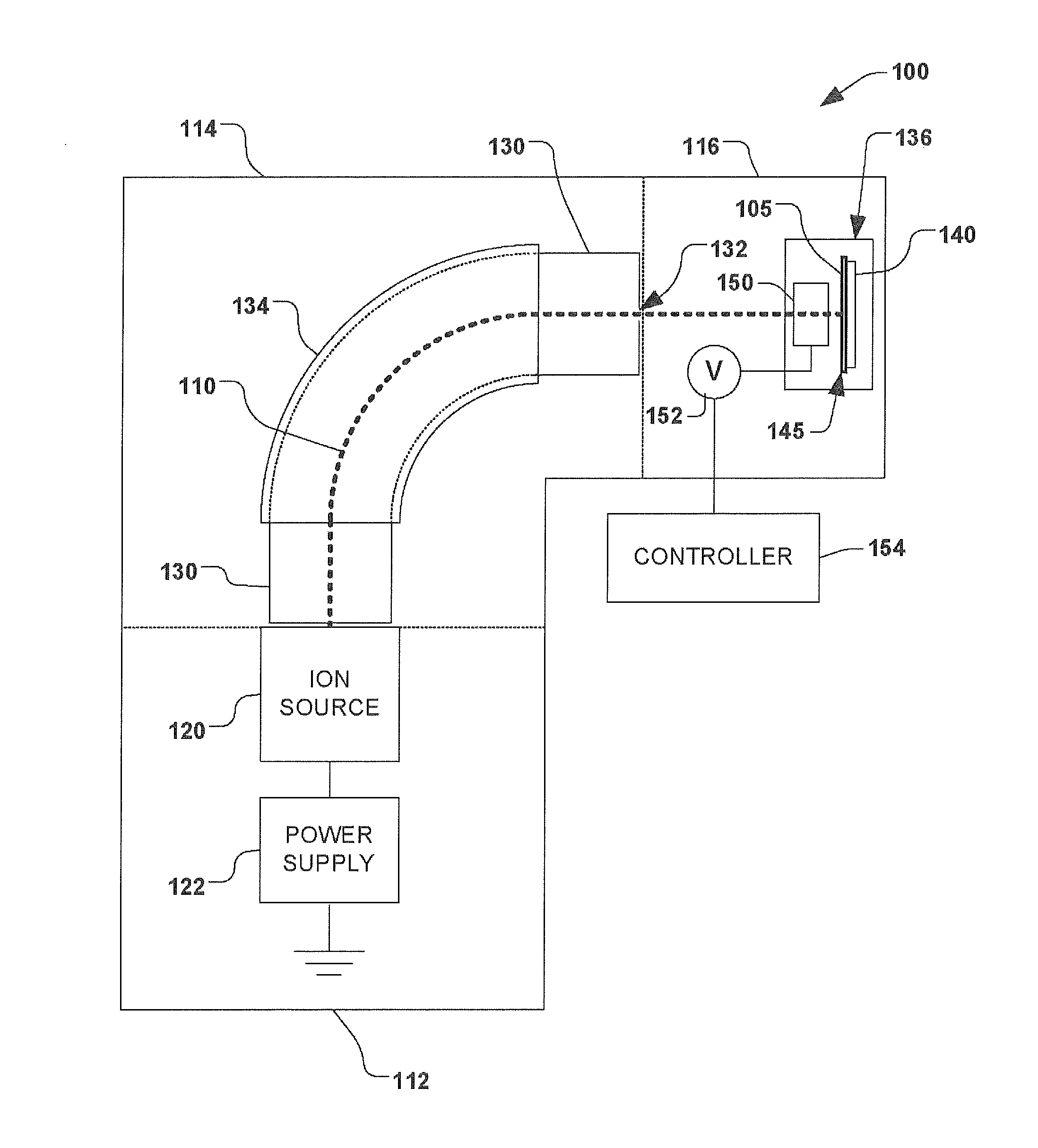
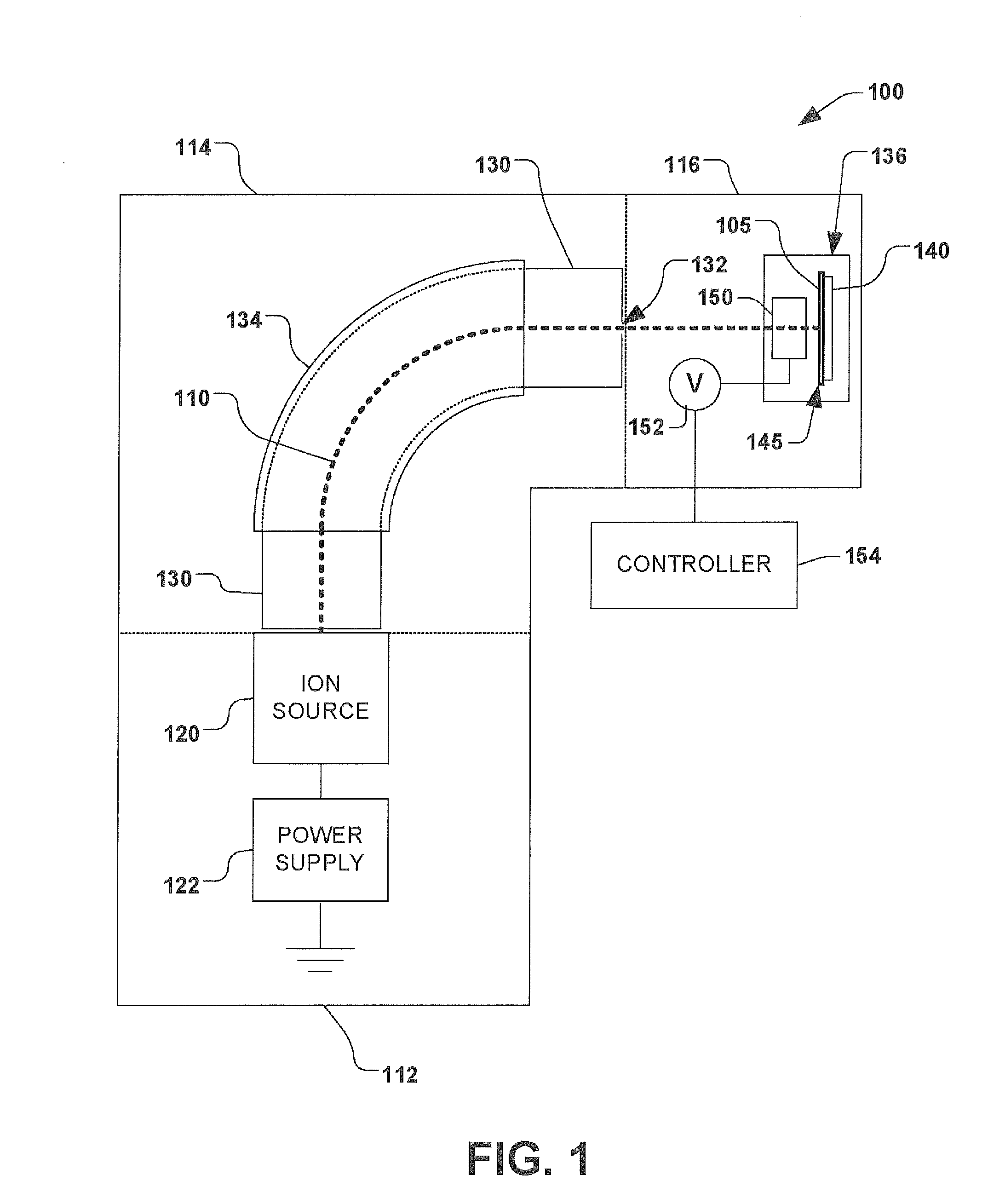
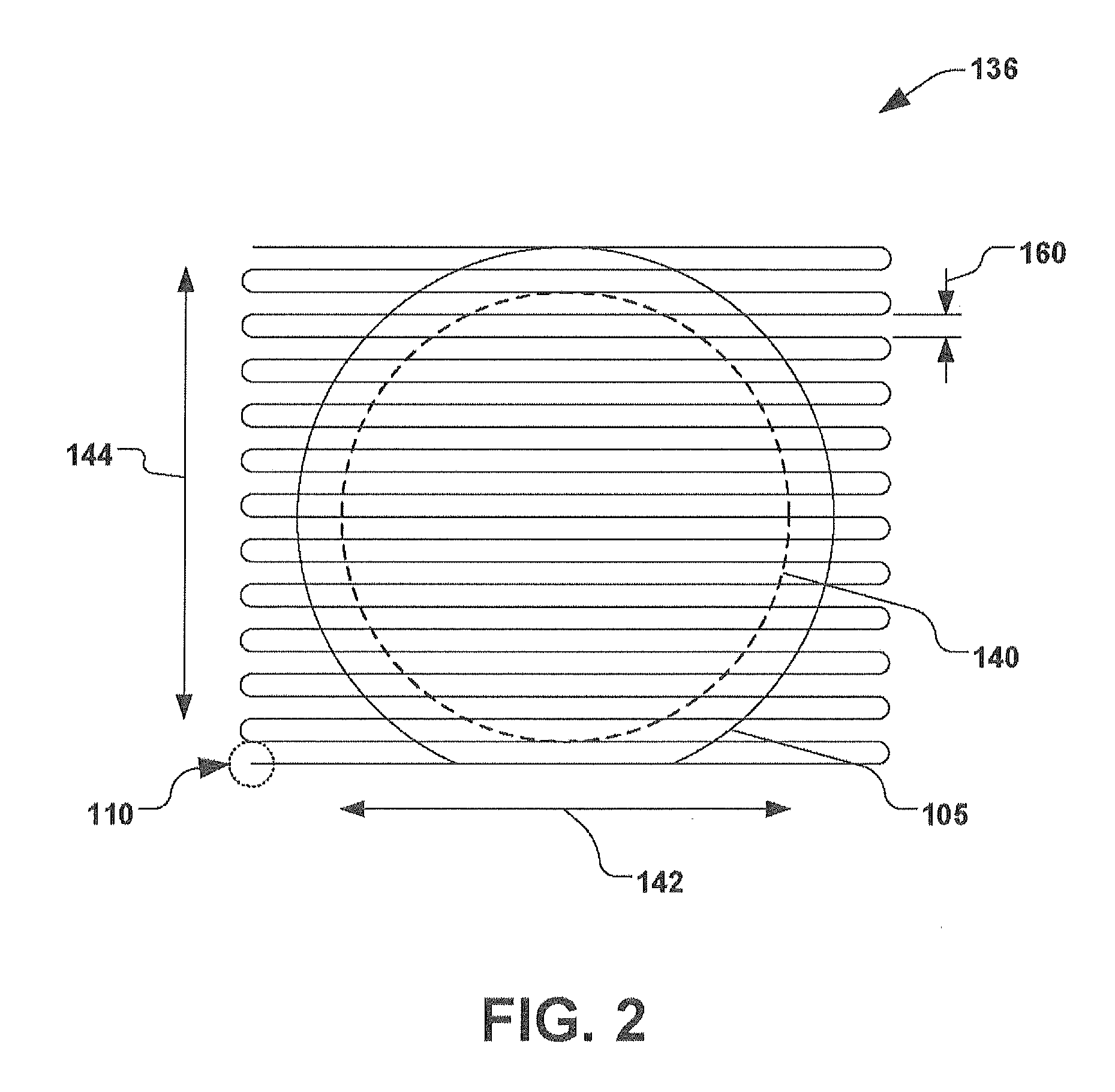
[0010]According to one embodiment of the invention, the supplemental scanning system provides a dithering of the ion beam in a direction that is different than a fast scan direction of the end station. Further, in one embodiment a frequency of the dithering is substantially greater than a fast scan frequency of the end station, thereby resulting in an ion beam profile along the fast scan axis that is larger than the ion beam itself. The increased ion beam profile or “scan width” provides for improved dose uniformity without a loss of system productivity or throughput.
[0011]According to another embodiment of the invention, a method of implanting a workpiece is provided. The method comprises directing an ion beam toward an end station that is configured to hold or support the workpiece, and scanning the end station two-dimensionally with respect to the incoming ion beam. The two-dimensional scanning comprises scanning the end station along a fast scan axis having a fast scan direction and along a slow scan axis having a slow scan direction that are different from one another. The method further comprises scanning the ion beam in a supplemental fashion along another axis having a direction that is different than the fast scan direction. This supplemental scanning is performed while the end station is being scanned past the ion beam in the fast scan direction, thereby increasing an effective scan width of the ion beam during mechanical scanning.

Problems solved by technology

Due to the slower reciprocating motion of the workpiece, the two dimensional scanning system is not capable of the same scanning speeds as the batch tools.
Further, because of this slower scan speed the number of scan lines across the wafer is reduced, and therefore the micro-uniformity of the dose across the wafer is an issue to be considered.
Although this solution can be effective for controlling uniformity, it has a disadvantage that the decreasing the pitch of the scan lines increases the total implant time because of the corresponding greater number scan passes required to completely scan the workpiece.
Thus the prior art solution provides for sufficient uniformity, but such improvement comes at the expense of a decrease in the productivity of the tool.

Method used


Image

  • Use of Beam Scanning to Improve Uniformity and Productivity of a 2D Mechanical Scan Implantation System
  • Use of Beam Scanning to Improve Uniformity and Productivity of a 2D Mechanical Scan Implantation System
  • Use of Beam Scanning to Improve Uniformity and Productivity of a 2D Mechanical Scan Implantation System

Examples


Embodiment Construction

FIG. 12 is a graph illustrating an interrelationship between a minimum implant time and a scan width due to dithering according to one embodiment of the invention;

[0028]FIG. 13 is a graph illustrating a plurality of effective ion beam profiles due to dithering according to the invention, wherein one curve illustrating a linear type dithering movement of the ion beam along a third axis, and the other two curves illustrate differing non-linear dithering movements according to alternative embodiments of the invention;

[0029]FIG. 14 is a graph illustrating how linear and non-linear dithering movements of the ion beam according to the invention provide differing levels of predicted dose uniformity; and

[0030]FIG. 15 is a flow chart illustrating a method of improving dose uniformity across a workpiece in a two-dimensional scanning system employing a dithering movement of an ion beam along a third axis having a direction that is different than a fast scan axis direction according to one embo...


PUM


Abstract

An ion implantation system includes a beamline configured to direct an ion beam toward an end station configured to hold or support a workpiece, and a scanning system. The scanning system is configured to scan the end station past the ion beam in a two-dimensional fashion comprising a first scan axis along a first direction and a second scan axis along a second direction that is different than the first direction. The system further includes a supplemental scanning component operably associated with the scanning system, and configured to effectuate a scanning of the ion beam with respect to the end station along a third scan axis having a third direction that is different than the first direction.

Description

REFERENCE TO RELATED APPLICATION[0001]This application claims priority to and the benefit of U.S. Provisional Application Ser. No. 61 / 222,671 which was filed Jul. 2, 2009, entitled USE OF BEAM SCANNING TO IMPROVE UNIFORMITY AND PRODUCTIVITY OF A 2D MECHANICAL SCAN IMPLANTATION SYSTEM, the entirety of which is hereby incorporated by reference as if fully set forth herein.FIELD OF THE INVENTION[0002]The present invention relates generally to ion implantation systems and methods associated therewith, and more specifically to a system and method for improving uniformity and productivity of a 2D mechanical scan implantation system.BACKGROUND OF THE INVENTION[0003]In the semiconductor industry, various manufacturing processes are typically carried out on a substrate (e.g., a semiconductor wafer) in order to achieve various results on the substrate. Processes such as ion implantation, for example, can be performed in order to obtain a particular characteristic on or within the substrate, s...

Claims


Application Information

Patent Timeline
IPC IPC(8): H01J37/317H01J37/147H01J37/20
CPCH01J37/1472H01J37/20H01J2237/24542H01J2237/20228H01J37/3171
Inventor RAY, ANDY
Owner AXCELIS TECHNOLOGIES
Learn More