Dereverberation apparatus, dereverberation method, dereverberation program, and recording medium

Active Publication Date: 2011-01-06
NIPPON TELEGRAPH & TELEPHONE CORP
View PDF2 Cites 33 Cited by
  • Summary
  • Abstract
  • Description
  • Claims
  • Application Information

AI Technical Summary

Benefits of technology

[0022]In the following description, the covariance matrix H(r) is a covariance matrix for the observation signal handled in the related art 1. Assuming that two microphones collect one audio signal, Xt−1=[x−t−1(1), . . . , x−1−K(1), x−t−1(2), . . . , x−t−K(2)], where x−t(1) is a column vector composed of short-time frames of xt(1) having a length of N (x−t(1)=[xt+1(1), . . . , xt+N−1(1)]T), and xt(1) and xt(2) are observation signals collected by microphones for the first channel and the second channel, respectively. T represents transposition of a matrix or a vector. K represents the length of a prediction filter (estimated dereverberation filter). rt represents a covariance matrix E{s−ts−tT} for a column vector s−t=[st, st+1, st+N−1]T composed of short time frames of the audio signal (rt=E{s−ts−tT}), where E{·} represents an expected value function. In general, the covariance matrix rt is not known, and therefore, an estimated value determined by the estimating section 104 on the basis of the sound source model stored in the sound source model storage section 108 is used.
[0023]In general, at least theoretically, the length of K of the prediction filter has to be equal to the length of the room impulse response. Therefore, the size of the covariance matrix H(r) is extremely large. However, if it is assumed that the audio signal is a stationary signal, the covariance matrix approximates to a correlation matrix, and therefore, a fast calculation method, such as the fast Fourier transform, can be used. However, if this assumpt

Problems solved by technology

Thus, the maximization of the value of the optimization function requires an enormous amount of calculation time.
However, if this assumption is applied to a time-varying signal, such as a voice signal, the calculation precision of the dereverberation disadvantageously decreases.
As described above, the

Method used


Image

  • Dereverberation apparatus, dereverberation method, dereverberation program, and recording medium
  • Dereverberation apparatus, dereverberation method, dereverberation program, and recording medium
  • Dereverberation apparatus, dereverberation method, dereverberation program, and recording medium

Examples


embodiment 1

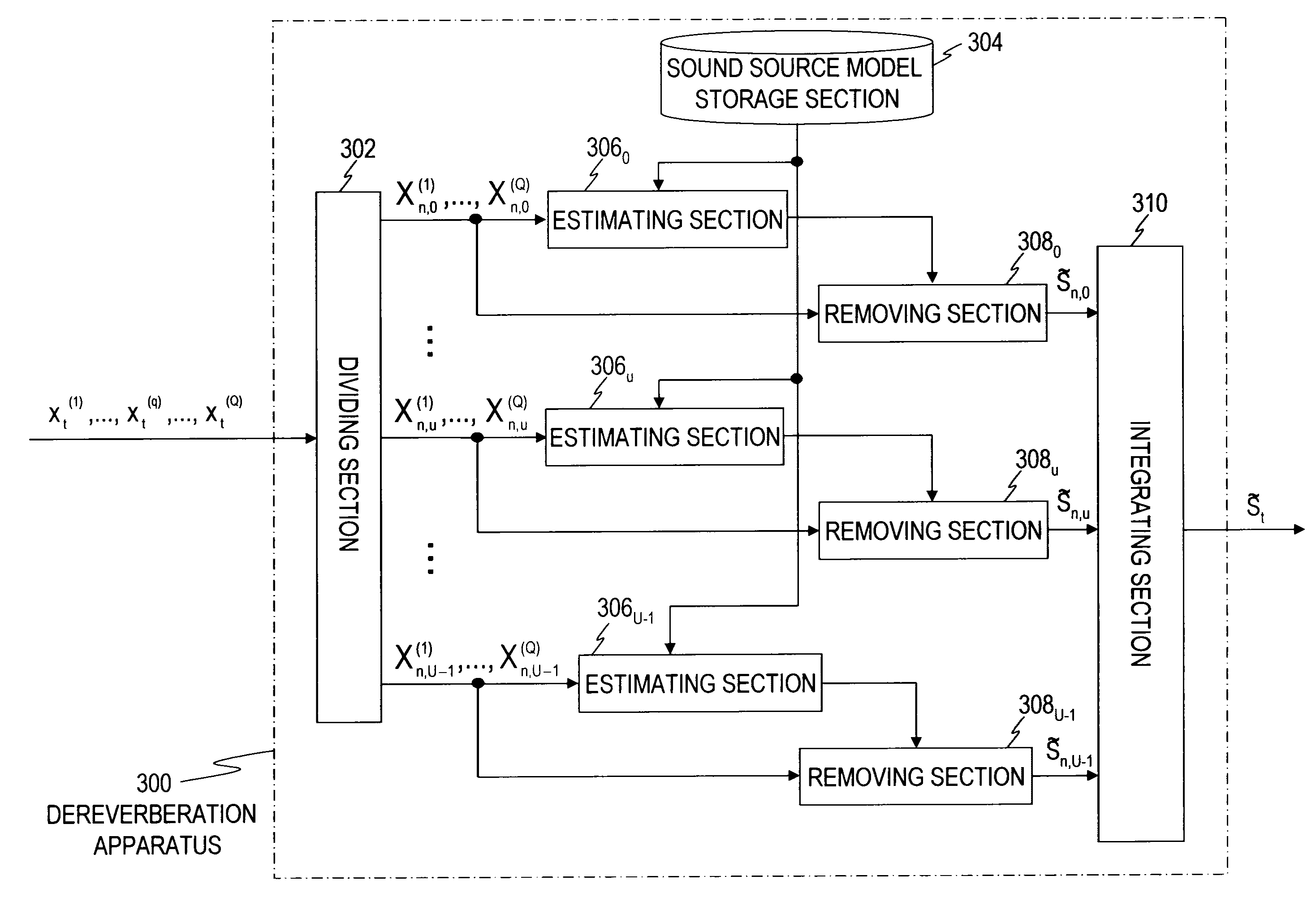
[0038]FIG. 3 is a block diagram showing a dereverberation apparatus 300 according to an embodiment 1, and FIG. 4 shows a general flow of a process performed by the dereverberation apparatus 300. As shown in FIG. 3, the dereverberation apparatus 300 according to the embodiment 1 comprises a dividing section 302 that divides an observation signal into U frequency bands, a sound source model storage section 304, an estimating section 306u (u=0, . . . , U−1) provided for each frequency band, a removing section 308u provided for each frequency band, and an integrating section 310.

[0039]The dividing section 302 divides the observation signal into individual frequency bands and down-samples the observation signals to output frequency-specific observation signals. The dividing section 302 according to the embodiment 1 divides the observation signal on a frequency band basis by applying a short-time analysis window to the observation signal by temporally shifting the short-time analysis wind...

embodiment 2

[0083]In the embodiment 1, the observation signal is convolved with the dereverberation filter estimated for each frequency band to achieve dereverberation. However, as is known, dereverberation carried out by estimating the reverberation signal and determining a difference signal that is the difference between the energy of the observation signal and the energy of the reverberation signal is less susceptible to the estimation error of the dereverberation filter than the dereverberation method according to the embodiment 1. For example, such a method is described in K. Kinoshita, T. Nakatani, and M. Miyoshi, “Spectral subtraction steered by multi-step forward linear prediction for single channel speech dereverberation,” Proc. ICASSP-2006, vol. I, pp. 817-820, May, 2006. An embodiment 2 is based on this concept.

[0084]A dereverberation apparatus 400 according to the embodiment 2 will be described. FIG. 5 shows an exemplary functional configuration of the dereverberation apparatus 400,...

embodiment 3

[0090]FIG. 7 shows an exemplary functional configuration of a dereverberation apparatus 500 according to an embodiment 3. The dereverberation apparatus 500 differs from the dereverberation apparatus 300 primarily in that (1) a dividing section 502 of the dereverberation apparatus 500 divides the time-domain observation signal into frequency bands by using subband division, whereas the dividing section 302 of the dereverberation apparatus 300 divides the time-domain observation signal into frequency bands by using conversion into the frequency-domain signal using temporal shifting, and (2) a removing section and an integrating section of the dereverberation apparatus 500 according to this embodiment performs their respective processings in the time domain, whereas the removing section and the integrating section of the dereverberation apparatus 300 perform their respective processings in the frequency domain.

[0091]A signal resulting from the subband division is referred to as a subba...


PUM


Abstract

A sound source model storage section stores a sound source model that represents an audio signal emitted from a sound source in the form of a probability density function. An observation signal, which is obtained by collecting the audio signal, is converted into a plurality of frequency-specific observation signals each corresponding to one of a plurality of frequency bands. Then, a dereverberation filter corresponding to each frequency band is estimated by using the frequency-specific observation signal for the frequency band on the basis of the sound source model and a reverberation model that represents a relationship for each frequency band among the audio signal, the observation signal and the dereverberation filter. A frequency-specific target signal corresponding to each frequency band is determined by applying the dereverberation filter for the frequency band to the frequency-specific observation signal for the frequency band, and the resulting frequency-specific target signals are integrated.

Description

TECHNICAL FIELD[0001]The present invention relates to a dereverberation apparatus, a dereverberation method and a dereverberation program and a recording medium for removing a reverberation signal from an observation signal.BACKGROUND ART[0002]In the following description, a signal emitted from a sound source is referred to as an audio signal, and an audio signal produced in a reverberant room and collected by a plurality of sound collecting means (microphones, for example) is referred to as an observation signal. The observation signal is the audio signal on which a reverberation signal is superimposed. It is difficult to extract characteristics of the original audio signal from the observation signal, and the resulting sound has a decreased clarity. A dereverberation processing removes the superimposed reverberation signal from the observation signal to facilitate extraction of the characteristics of the original audio signal and recover the sound clarity. This technique can be ap...

Claims


Application Information

Patent Timeline
IPC IPC(8): H04B3/20G10L21/0208
CPCG10L2021/02082H04S7/305G10L21/0208G10L21/0232G10L21/02
Inventor NAKATANI, TOMOHIROYOSHIOKA, TAKUYAKINOSHITA, KEISUKEMIYOSHI, MASATO
Owner NIPPON TELEGRAPH & TELEPHONE CORP
Why Eureka
Try Eureka