Fuel cell apparatus and method of fabrication

a fuel cell and apparatus technology, applied in the field of fuel cells, can solve the problems of insufficient power generation for inadequately short duration, unwieldy power sources currently employed in mobile devices, and insufficient renewable power sources for low-power devices, etc., and achieve the effect of cost-effective production and distribution and easy manufacturing

Inactive Publication Date: 2011-01-06
MARKOSKI LARRY J +2
View PDF98 Cites 11 Cited by
  • Summary
  • Abstract
  • Description
  • Claims
  • Application Information

AI Technical Summary

Benefits of technology

[0017]The invention teaches a variety of fuel cell, fuel cell stack systems, and fuel cell power systems, as well as techniques and mechanisms for manufacturing such devices. Certain embodiments of the present invention offer dramatic improvements over prior art fuel cell technologies in system performance, usability, and expense. In particular, certain fuel cells of the present invention demonstrate efficiency, are lightweight, relatively easy to manufacture, and cost-effective to produce and distribute. These embodiments are particularly well-suited to micro fuel cell applications (100 watt and below) such as portable electronic devices, including lap top computers, personal digital assistants, mobile phones, and other such products. Other suitable applications for the fuel cells described herein shall be readily apparent to those skilled in the art.

Problems solved by technology

Existing renewable power sources for low-power devices, such as handheld electronics or other portable devices, have failed to keep pace with the increasing sophistication of such electronics.
The power sources currently employed in mobile devices, including various types of chemical batteries such as lithium ion or nickel cadmium batteries, are unwieldy, generate insufficient power for inadequately short duration, and require untenably long recharge periods.
These limitations impose severe restrictions on the functionality of the devices they power: e.g., users are forced to recharge units at untenably short intervals, and the weight of existing batteries renders mobile devices much larger and heavier than desirable.
While increasing the energy density for PEM systems is relative easy to achieve for large systems, decreasing the size and weight of the BOP and fuel cell stack 150 has been shown to be somewhat problematic for sub 100 Watt levels.
Inefficiency can be at least partially attributed to the volume of the fuel cell stack within these low power PEM fuel cell systems.
Moreover, such stacks are physically weighty, by virtue of the thick machined graphite bipolar plates and end plates typically used in construction.
This feature of the prior art PEM fuel cell technology is particularly problematic for mobile devices, for which low weight / volume form factors constitute a critical selling feature.

Method used


Image

  • Fuel cell apparatus and method of fabrication
  • Fuel cell apparatus and method of fabrication
  • Fuel cell apparatus and method of fabrication

Examples


Embodiment Construction

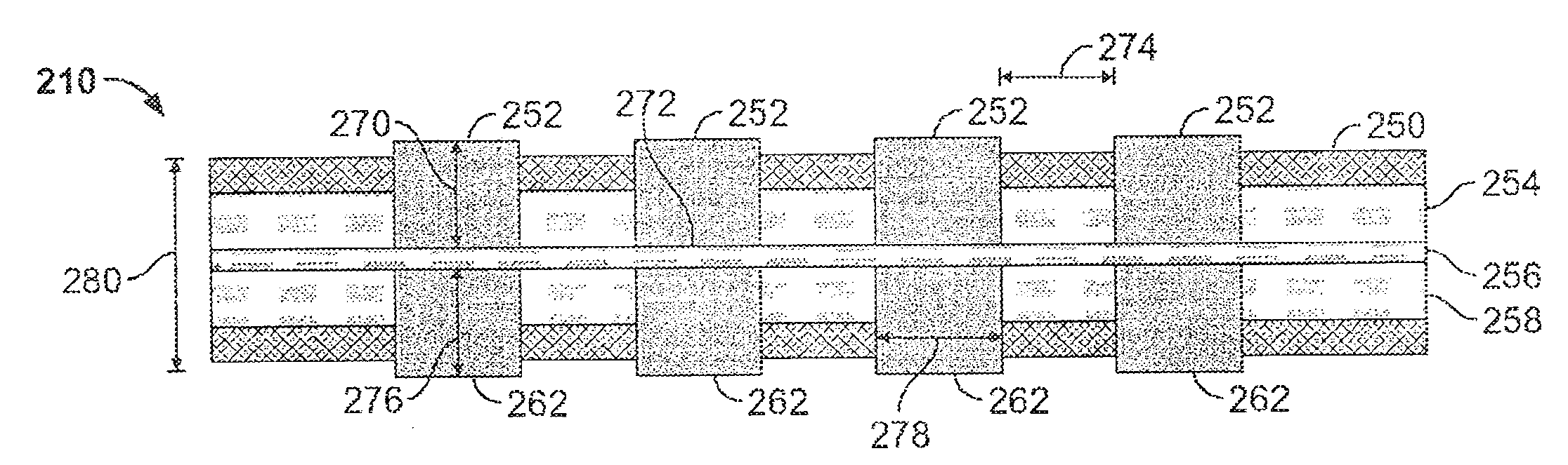
[0037]FIG. 6 illustrates schematically a design of a fuel cell stack 200 according to one embodiment of the present invention. The fuel cell stack 200 includes an anode end plate 202, a cathode end plate 204, two membrane electrode assemblies 206 and 208, and a bipolar plate 210. Opposite surfaces 212 and 214 of the MEA 206 are flush with conductive surfaces of the anode end plate 202 and the bipolar plate 210, respectively. Opposite surfaces 216 and 218 of the MEA 208 are flush with conductive surfaces of the cathode end plate 204 and the bipolar plate 210, respectively. (number).

[0038]FIG. 7 illustrates a 4-channel in-plane conductive composite end plate 230 in accordance with one embodiment of the present invention. FIG. 7A provides a cross-sectional (side profile) schematic diagram of the 4-channel in-plane conductive composite end plate 230 of FIG. 7. As will be appreciated, the end plate 230 represents one possible generic configuration for both anode and cathode end plates su...


PUM

PropertyMeasurementUnit
thicknessaaaaaaaaaa
operating temperatureaaaaaaaaaa
thicknessaaaaaaaaaa

Abstract

A fuel cell is described. The fuel cell includes current collectors, each of which includes a substrate of lightweight material, such as Kapton material. Micro channels are formed via laser machining or chemical etching into the substrate. The current collectors further include conductive layers sputtered on the substrate, and protective coating on the conductive layers. A variety of materials are available for the conductive layers. The fuel cell so developed is particularly well suited to mobile applications, such as electronic devices.

Description

CROSS-REFERENCE TO RELATED APPLICATIONS[0001]The present invention claims priority to Markoski's U.S. provisional patent application No. 60 / 547,618, filed Feb. 24, 2004, entitled FUEL CELL APPARATUS AND METHOD OF FABRICATION, the entire contents of which are incorporated herein by reference.BACKGROUND OF THE INVENTION[0002]1. Field of the Invention[0003]The present invention relates to fuel cells. More specifically, the present invention teaches a variety of in-plane fuel cell current collectors embedded on flexible lightweight substrates and coupled to lightweight flow distributors, and methods for manufacturing same.[0004]2. Discussion of the Related Art[0005]Existing renewable power sources for low-power devices, such as handheld electronics or other portable devices, have failed to keep pace with the increasing sophistication of such electronics. The power sources currently employed in mobile devices, including various types of chemical batteries such as lithium ion or nickel ca...

Claims


Application Information

Patent Timeline
Patent Type & Authority Applications(United States)
IPC IPC(8): H01M8/04H01M4/88H01M8/24H01B1/24H01M4/86H01M8/02H01M8/10
CPCH01M8/0206H01M8/0213H01M8/0221H01M8/0228H01M8/0247Y02B90/18H01M8/2465H01M2008/1095H01M2250/30Y02E60/50H01M8/0263H01M8/2483Y02B90/10H01M8/2418
Inventor MARKOSKI, LARRY J.NATARAJAN, DILIPPRIMAK, ALEX
Owner MARKOSKI LARRY J
Why Eureka
Try Eureka