
Exhaust gas heat recovery unit and exhaust gas heat recovery method

Inactive Publication Date: 2011-01-13
TOYOTA JIDOSHA KK
View PDF2 Cites 9 Cited by
  • Summary
  • Abstract
  • Description
  • Claims
  • Application Information

AI Technical Summary

Benefits of technology

[0008]The invention provides an exhaust gas heat recovery unit and exhaust gas heat recovery method that makes it possible to recover heat efficiently by promptly heating a working fluid at a heater portion in a short time using exhaust gas in the case of cold starting of an engine.
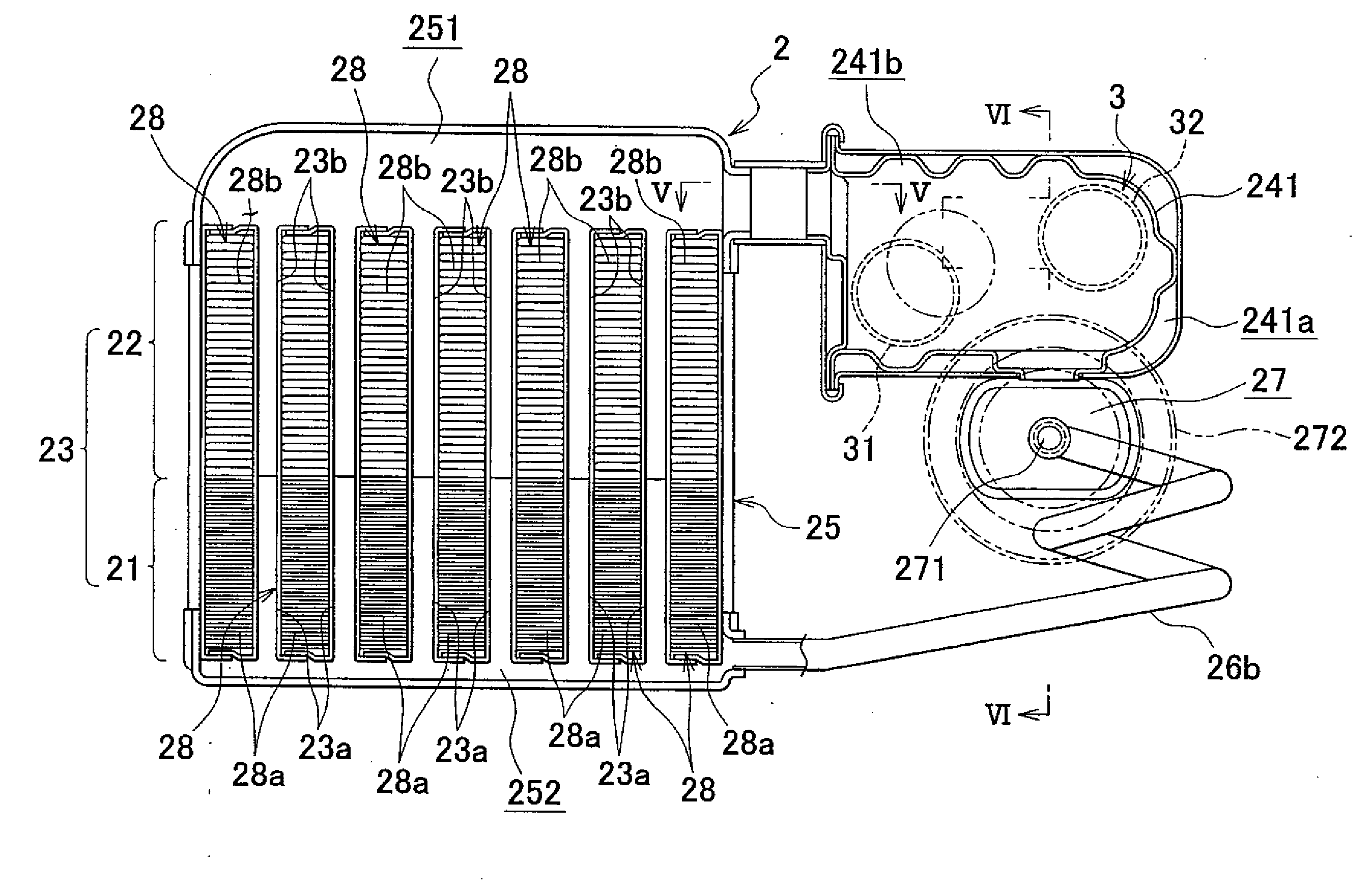
[0010]With this structure, the amount of heat that the fins on the heater portion receive is larger than the amount of heat that the fins on the evaporator portion receive. Therefore, in the case where the exhaust gas heat recovery unit is exposed to an ambient temperature of equal to or lower than the freezing temperature of the working fluid, for example, in the case of cold starting of the engine, a sufficient amount of heat of the exhaust gas is applied to the heater portion that stores the working fluid, and the working fluid in the heating portion is promptly heated by the sufficient amount of heat received from the exhaust gas. As a result, it is possible to smoothly circulate the working fluid to efficiently recover the heat with the use of the exhaust gas heat recovery unit, in the case of cold starting of the engine.
[0011]In addition, most part of the predetermined amount of heat received from the exhaust gas is covered by the heat received by the fins on the outer periphery of the heater portion due to the small pitch of the fins. Further, an increase in exhaust gas flow resistance due to the above-described small pitch is offset by setting the pitch of the fins on the outer periphery of the evaporator portion to a large pitch. As a result, it is possible to suppress an increase in back pressure, which is caused on the downstream side in the exhaust gas flow direction due to provision of the exhaust gas heat recovery unit.
[0014]With this structure, the pitch of the fins on the outer periphery of the heater portion of the heat pipe is set in such a manner that the temperature of the working fluid, which is exposed to an ambient temperature of equal to or lower than the freezing temperature of the working fluid at cold starting time of the engine, is increased to a temperature equal to or higher than the freezing temperature by the amount Qex of heat that is received from the exhaust gas within the predetermined period from cold starting of the engine. Therefore, in the case where the exhaust gas heat recovery unit is exposed to an ambient temperature of equal to or lower than the freezing temperature of the working fluid, for example, in the case of cold starting of the engine, a sufficient amount of heat of the exhaust gas is applied to the heater portion that stores the working fluid, and the working fluid in the heating portion is promptly heated by the sufficient amount of heat received from the exhaust gas. As a result, it is possible to smoothly circulate the working fluid to efficiently recover the heat with the use of the exhaust gas heat recovery unit in the case of cold starting of the engine.
[0016]The pitch of the fins on the outer periphery of the heater portion of the heat pipe is set in such a manner that the temperature of the working fluid, which is exposed to an ambient temperature of equal to or lower than the freezing temperature of the working fluid at cold starting time of the engine, is increased to a temperature equal to or higher than the freezing temperature by the amount Qex of heat that is received from the exhaust gas within the predetermined period from cold starting of the engine. Therefore, in the case where the exhaust gas heat recovery unit is exposed to an ambient temperature of equal to or lower than the freezing temperature of the working fluid, in the case of cold starting of the engine, a sufficient amount of heat of the exhaust gas is applied to the heater portion that stores the working fluid, and the heat of the exhaust gas applied to the heater portion is sufficiently transferred to the working fluid in the fluid passage. Thus, the working fluid in the heating portion and the working fluid in the fluid passage are promptly heated by the sufficient amount of heat received from the exhaust gas. As a result, it is possible to smoothly circulate the working fluid to efficiently recover the heat with the use of the exhaust gas heat recovery unit in the case of cold starting of the engine.
[0018]With this structure, an increase in the exhaust gas flow resistance, which is caused due to the small pitch of the fins on the outer periphery of the heater portion, is offset by setting the pitch of the fins on the outer periphery of the evaporator to a large pitch. Therefore, it is possible to efficiently suppress an increase in back pressure, which is caused on the downstream side in the exhaust gas flow direction due to provision of the exhaust gas heat recovery unit.

Problems solved by technology

Therefore, it takes a long time for the heater to heat the working fluid using the heat received from exhaust gas.
Accordingly, for example, in the case of cold starting of the engine, it is not possible to heat the working fluid quickly to circulate it smoothly.
As a result, it is not possible to efficiently recover the heat with the use of the exhaust gas heat recovery unit.

Method used


Image

  • Exhaust gas heat recovery unit and exhaust gas heat recovery method
  • Exhaust gas heat recovery unit and exhaust gas heat recovery method
  • Exhaust gas heat recovery unit and exhaust gas heat recovery method

Examples


Embodiment Construction

[0035]Hereinafter, an example embodiment of the invention will be described with reference to the accompanying drawings.

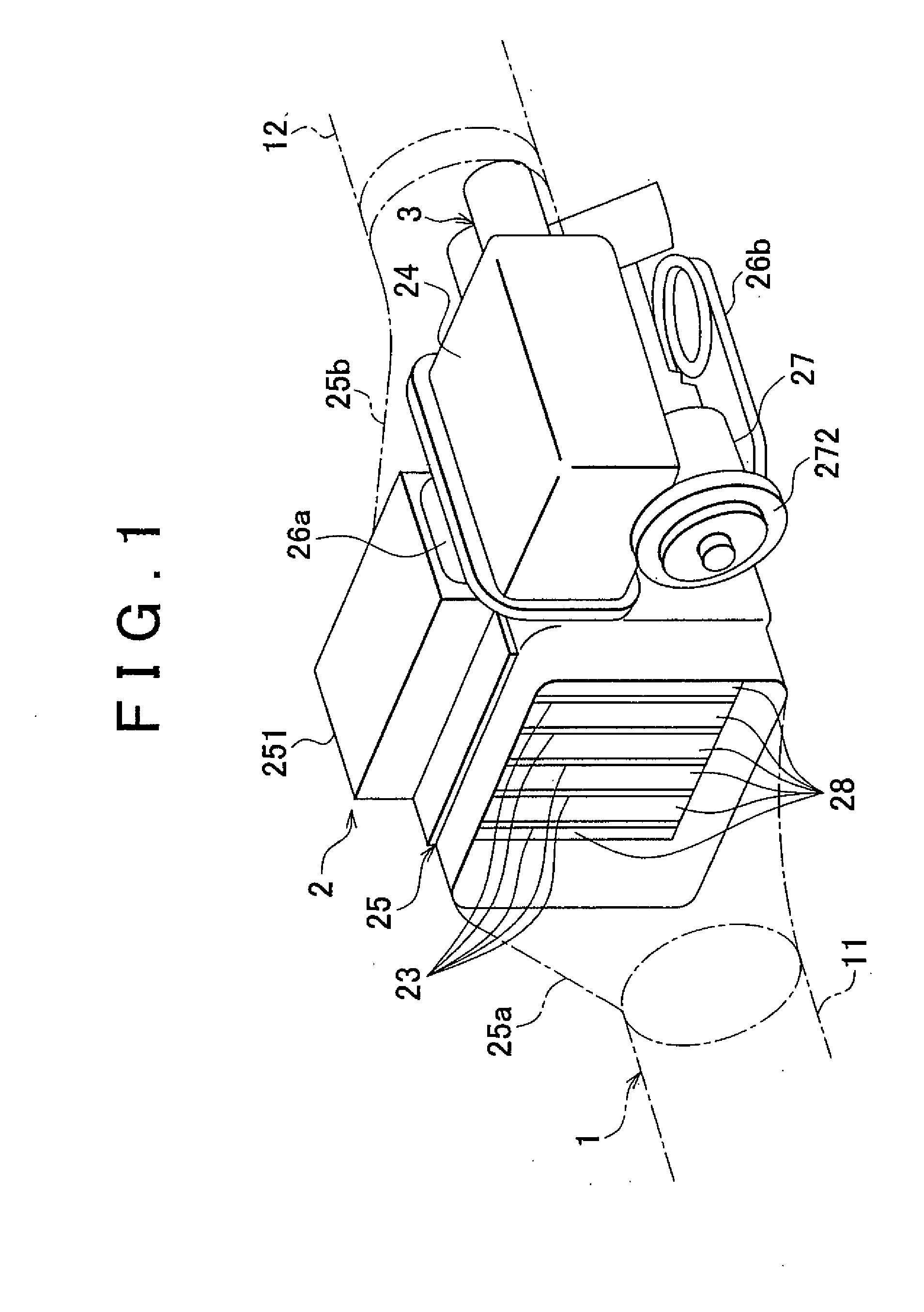
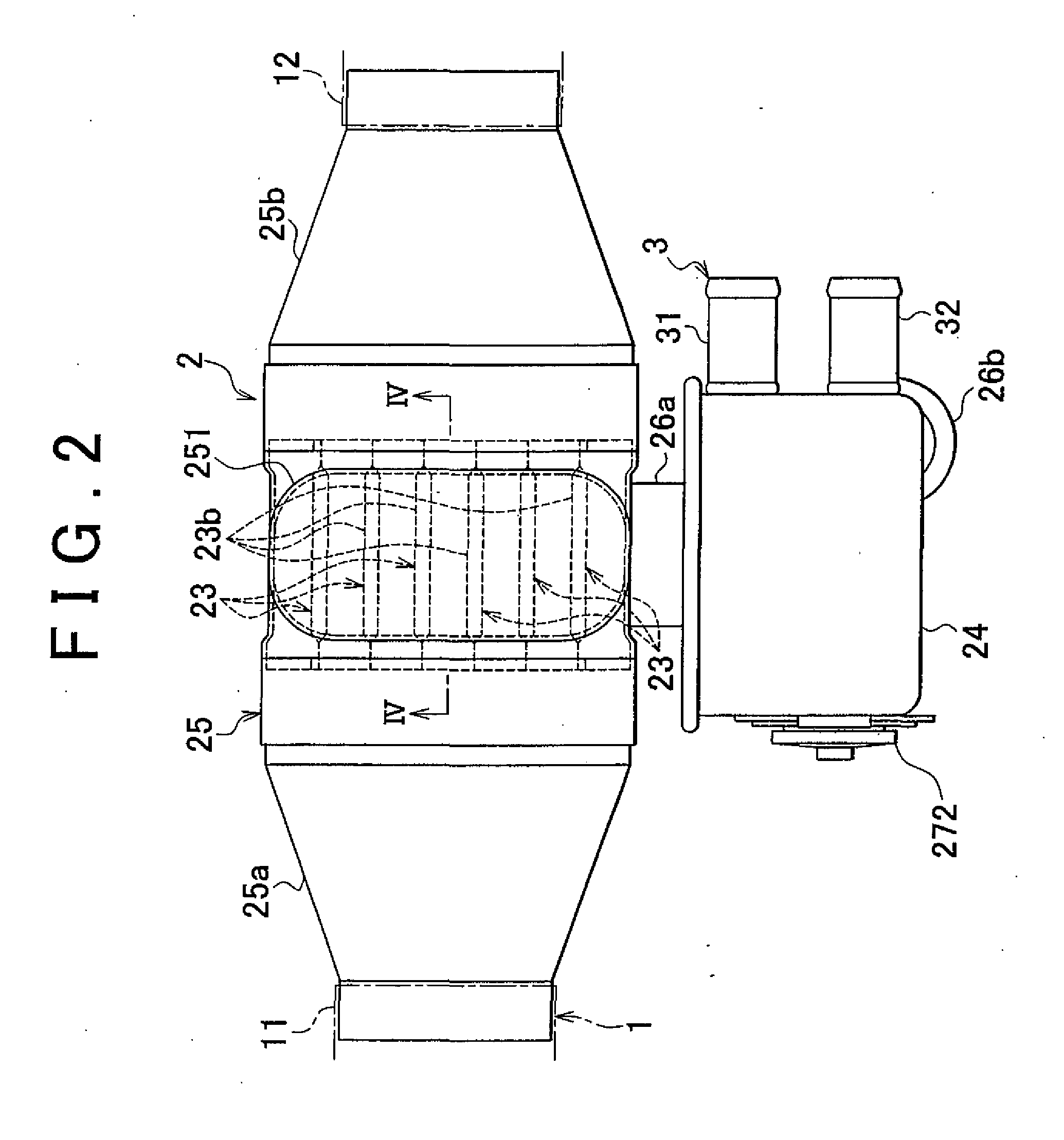
[0036]FIG. 1 and FIG. 2 show an exhaust pipe 1 of an automobile that is provided with an exhaust gas heat recovery unit 2 according to an example embodiment of the invention. The exhaust gas heat recovery unit 2 is provided midway in the exhaust pipe 1. More specifically, the exhaust pipe 1 is partitioned into an upstream-side exhaust pipe conduit 11 and a downstream-side exhaust pipe conduit 12 by the exhaust gas heat recovery unit 2. An upstream-side connector 25a, which is fitted to an evaporation-side case 25 (described later in detail) of the exhaust gas heat recovery unit 2 at a portion on the upstream side in the exhaust gas flow direction, is connected to the upstream-side exhaust pipe conduit 11. A downstream-side connector 25b, which is fitted to the evaporation-side case 25 at a portion on the downstream side in the exhaust gas flow direction, is connect...


PUM


Abstract

An exhaust gas heat recovery unit includes a plurality of heat pipes (23) each of which includes a heater-side heat pipe portion (23a) positioned on the side of a heater (21) which heats pure water using heat of exhaust gas discharged from an engine and an evaporator-side heat pipe portion (23b) positioned on the side of an evaporator (22) which evaporates the pure water, heated at the heater-side heat pipe portion (23a), using the heat of the exhaust gas. The pitch of heater-side corrugated fins (28a) on the outer periphery of the heater-side heat pipe portion (23a) is set to substantially half the pitch of evaporator-side corrugated fins (28b) on the outer periphery of the evaporator-side heat pipe portion (23b).

Description

BACKGROUND OF THE INVENTION[0001]1. Field of the Invention[0002]The invention relates to an exhaust gas heat recovery unit and exhaust gas heat recovery method used for vehicles such as automobiles.[0003]2. Description of the Related Art[0004]There is a related technology in which the heat of exhaust gas discharged from an engine of a vehicle is recovered based on heat pipe principle and the recovered exhaust gas heat is used to promote warming-up of the engine.[0005]For example, Japanese Patent Application Publication No. 04-45393 (JP-A-04-45393) describes a heat exchanger of the loop heat pipe type, which operates on heat pipe principle. This heat exchanger includes a sealed circulation passage that forms a closed loop, an evaporable and condensable working fluid that is hermitically sealed in the circulation passage, an evaporator that is provided in the circulation passage and that evaporates the working fluid using externally transferred heat, and a condenser that is arranged a...

Claims


Application Information

Patent Timeline
IPC IPC(8): F01K23/06
CPCF01N5/02F28D15/0233F28D15/0266F28F2215/04F28F1/126Y02T10/16F28D21/0003Y02T10/12
Inventor TOI, MASAOMABUCHI, TOMOKITOKI, HIROYUKIYAMANAKA, YASUTOSHI
Owner TOYOTA JIDOSHA KK
Learn More