
Motor controller and electric power steering system

Active Publication Date: 2011-01-13
JTEKT CORP
View PDF6 Cites 17 Cited by
  • Summary
  • Abstract
  • Description
  • Claims
  • Application Information

AI Technical Summary

Benefits of technology

[0014]The invention has been made to solve the above problem and an object of the invention is to provide a motor controller and an electric power steering system, with which it is possible to improve the voltage utilization factor while ensuring smooth rotation of a motor and detection of electric current with high accuracy.
[0016]With this configuration, even when an electric current undetectable phase occurs, in which the electric current cannot be detected by the electric current sensor, it is possible to estimate the phase current value of the electric current undetectable phase by the blind estimation. In addition, when the phase current values of the two phases other than the electric current undetectable phase are detected, the switching state of the switching arm of the electric current undetectable phase is maintained, that is, switching operation thereof is not performed, so that it is possible to prevent the inclusion of the noise caused by the switching operation. As a result, even when limitation of the voltage to secure the detection time for detecting the phase current values of all the three phases (U, V, and W) is not imposed, it is ensured that the electric current is detected with high accuracy and therefore, it is possible to improve the voltage utilization factor.
[0017]In addition, by compensating for the power loss caused by the switching operation of the FETs in the two phases other than the electric current undetectable phase, the balance between the electric current detectable phases and the electric current undetectable phase, in which the power loss caused by the switching operation does not occur, is maintained. As a result, it is possible to suppress the occurrence of the distortion in the waveforms of the interphase voltages between the electric current undetectable phase and the two phases other than the electric current undetectable phase, and to suppress the occurrence of the torque ripple caused by such a distortion, so that it is possible to ensure smooth rotation of the motor.
[0018]In addition, by limiting the timing of performing the switching loss compensation control to the time period, during which the electric current is detected in the blind estimation, and by inhibiting the performance of the compensation calculation in the electric current undetectable phase, which is the non-switched phase, it is possible to suppress the increase in the calculation load. As a result, it is possible to avoid the increase in the throughput required of the information processor, which is a constituent element of the control signal output device, and the accompanying increase in costs.

Problems solved by technology

However, such a mode of electricity supply requires feedback of the phase current values.
However, although the electric current is detected at the timing at which all the switching devices on the lower potential side are turned on, detection of the electric current requires a certain period of time.
In the case where the electric current undetectable phase occurs in this way, however, even when the phase current values of the two phases other than the electric current undetectable phase are detected, the switching devices are turned on and off in the electric current undetectable phase, which causes the noise therefrom to be included in the phase current values of the remaining two phases, of which the electric currents are detectable, which has been the cause of the deterioration in the accuracy in detecting the electric current in the blind estimation.

Method used


Image

  • Motor controller and electric power steering system
  • Motor controller and electric power steering system
  • Motor controller and electric power steering system

Examples


Embodiment Construction

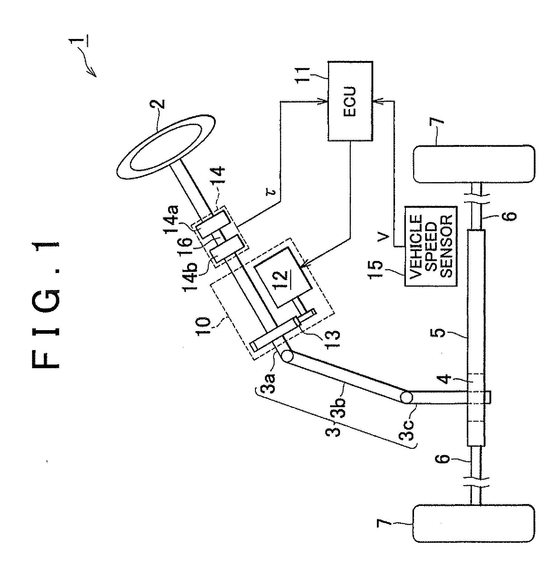
[0033]An embodiment of the invention will be described below with reference to the drawings. As shown in FIG. 1, in an electric power steering system (EPS) 1 of this embodiment, a steering shaft 3, to which a steering wheel 2 is fixed, is connected to a rack shaft 5 through a rack and pinion mechanism 4, so that the rotation of the steering shaft 3 caused by a steering operation is converted into a reciprocation of the rack shaft 5 via the rack and pinion mechanism 4. The steering shaft 3 is formed by connecting a column shaft 3a, an intermediate shaft 3b, and a pinion shaft 3c. The reciprocation of the rack shaft 5 caused by rotation of the steering shaft 3 is transmitted to knuckles (not shown) via tie rods 6 connected to both ends of the rack shaft 5, so that the steering angle of steered wheels 7, that is, the travel direction of a vehicle is changed.

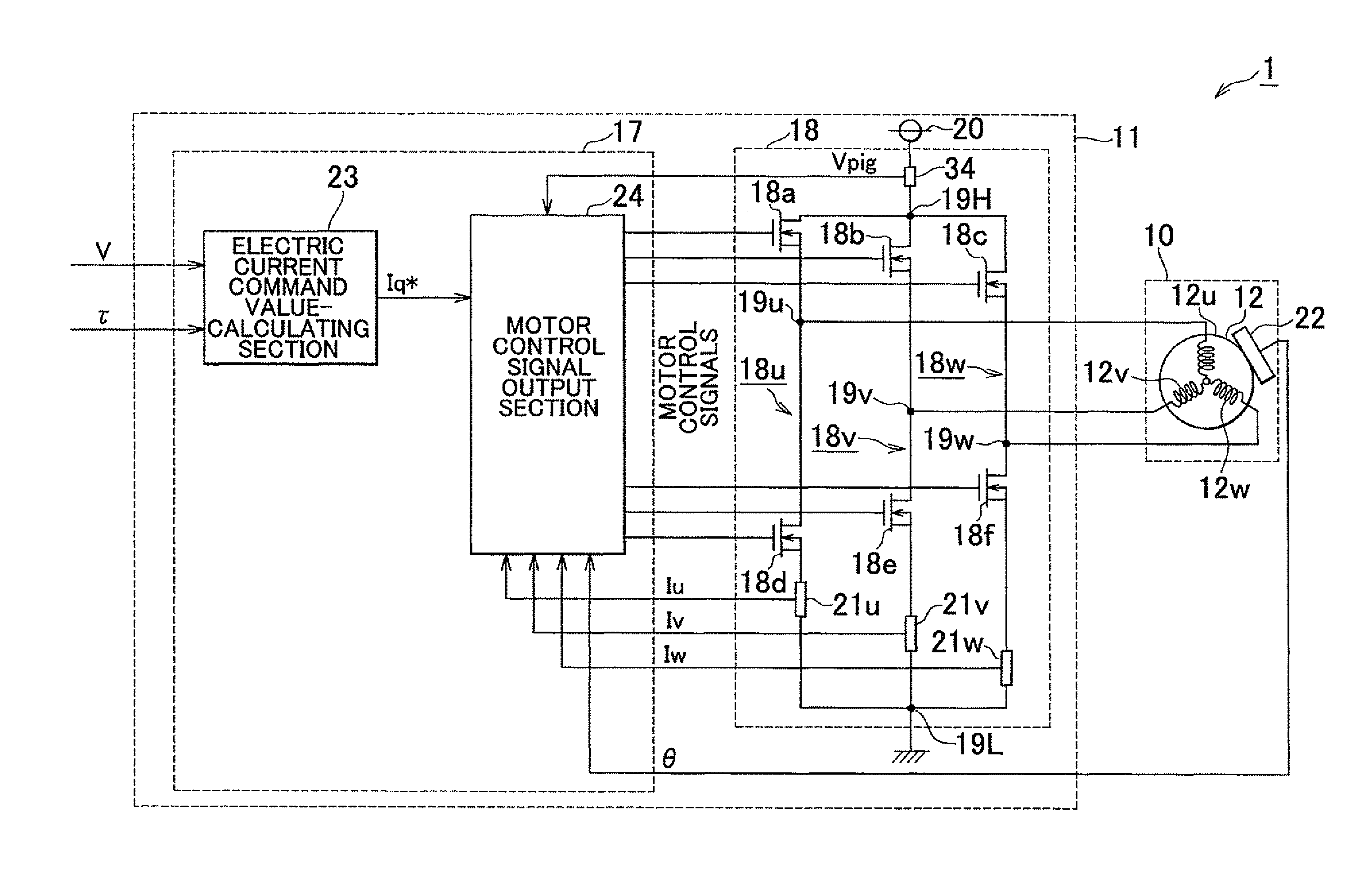
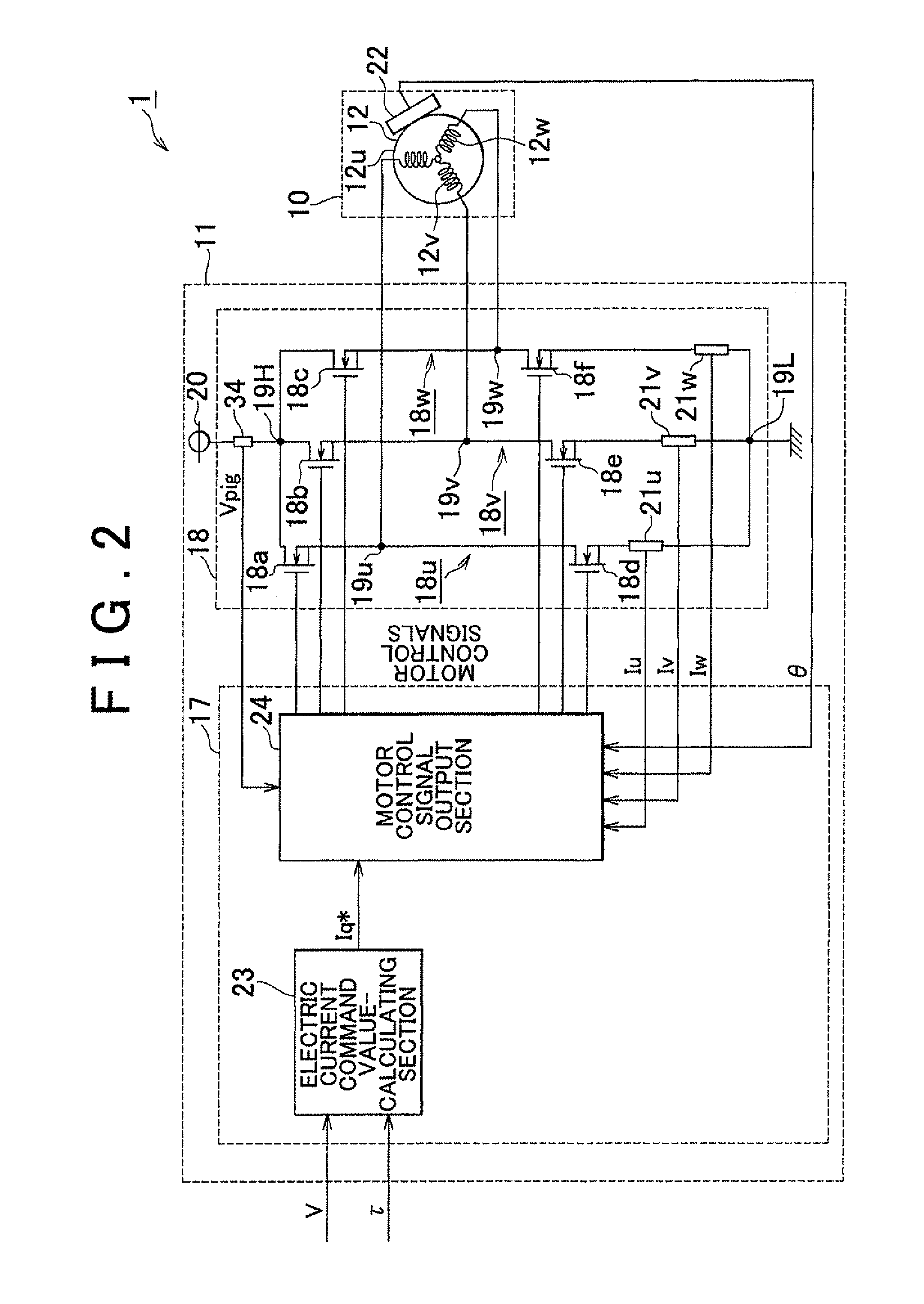
[0034]The EPS 1 includes an EPS actuator 10, which functions as a steering assist device that applies the assisting force to assis...


PUM


Abstract

A motor controller and an electric power steering system including the motor controller are provided. The motor controller has a microcomputer. When the on time of one of the lower potential-side FETs corresponding to the respective phases in a drive circuit becomes shorter than the detection time for detecting the phase current value, the microcomputer estimates the phase current value of the electric current undetectable phase based on the phase current values of the two phases other than the electric current undetectable phase corresponding to the relevant FET (blind estimation). When electric current detection is performed in the blind estimation, motor control signals are output, by which the switching state of the switching arm of the electric current undetectable phase is maintained and the power loss caused by the switching operation of the FETs in the two phases other than the electric current undetectable phase is compensated for.

Description

INCORPORATION BY REFERENCE[0001]The disclosure of Japanese Patent Application No. 2009-164047 filed on Jul. 10, 2009 including the specification, drawings and abstract is incorporated herein by reference in its entirety.BACKGROUND OF THE INVENTION[0002]1. Field of the Invention[0003]The invention relates to a motor controller and an electric power steering system.[0004]2. Description of the Related Art[0005]In a motor controller used in an electric power steering system (EPS) etc., a drive circuit (PWM inverter) for supplying electric power for drive to the a motor based on motor control signals is formed by connecting in parallel the switching arms corresponding to the respective phases, each switching arm including a pair of switching devices connected in series. As an example of such a motor controller, one, in which an electric current sensor is provided on the lower potential side (ground side) of each of the switching arms constituting the drive circuit, is available. Refer to...

Claims


Application Information

Patent Timeline
IPC IPC(8): B62D5/04H02P6/08B62D6/00B62D119/00H02M7/5387H02P6/06H02P6/16H02P6/28H02P21/00H02P21/14H02P21/18H02P21/22H02P21/24H02P23/14H02P27/04H02P27/08
CPCB62D5/046H02P21/145H02P21/04H02P21/16H02P27/08H02P21/22H02M7/5395H02M1/0009
Inventor MIKAMO, SATORUSAKAI, ATSUO
Owner JTEKT CORP
Learn More