
Method and apparatus for ac motor control

a technology of ac motor and control method, which is applied in the direction of motor/generator/converter stopper, process and machine control, electric/dynamo-electric converter starter, etc., can solve the problems of excessive peak power consumption during the start up period, soft starters do not support energy saving, and do not provide efficient means. , to achieve the effect of increasing motor efficiency

Active Publication Date: 2011-01-13
ELSA CJSC
View PDF50 Cites 12 Cited by
  • Summary
  • Abstract
  • Description
  • Claims
  • Application Information

AI Technical Summary

Benefits of technology

[0010]Responsive to a predetermined condition of the relative torque, the semiconductor switching unit is preferably set to the star configuration, and optionally phase control functionality is further enabled to reduce power consumption. In the event that the semiconductor switching unit is set to the delta configuration, phase control functionality is preferably enabled to reduce energy unit. In one embodiment energy is reduced responsive the calculated relative torque and the relative current. In another embodiment energy is reduced responsive to the calculated load angle, i.e. the angle between the EMF vector of the stator and the phase current vector of the stator.
[0012]In one embodiment, a voltage sensor and current sensors are provided for at least two of the three phases of input power, and each of motor torque and rotational speed is calculated responsive to the provided voltage and current sensors. In one embodiment a filter is further provided to increase motor efficiency during operation at rotational frequency less than nominal.

Problems solved by technology

Additionally, soft starters do not support energy savings during operation, nor do they provide an efficient means of braking since they do not participate in slowing down the motor when braking is required.
The start up period is extended and peak power consumption during the start up period is excessive.
Unfortunately, frequency converters are expensive and bulky, and many motors do not require such a broad range of control.

Method used


Image

  • Method and apparatus for ac motor control
  • Method and apparatus for ac motor control
  • Method and apparatus for ac motor control

Examples


Embodiment Construction

[0024]Before explaining at least one embodiment of the invention in detail, it is to be understood that the invention is not limited in its application to the details of construction and the arrangement of the components set forth in the following description or illustrated in the drawings. The invention is applicable to other embodiments or of being practiced or carried out in various ways. Also, it is to be understood that the phraseology and terminology employed herein is for the purpose of description and should not be regarded as limiting.

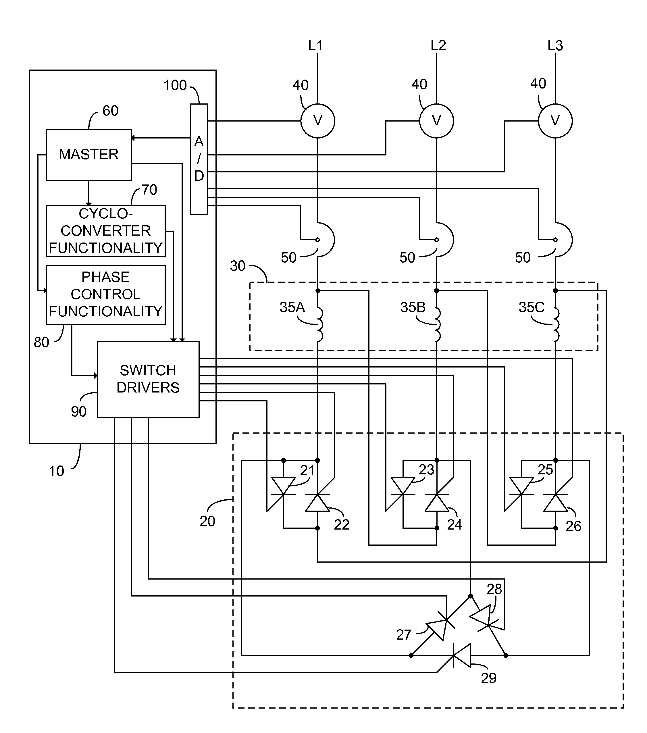
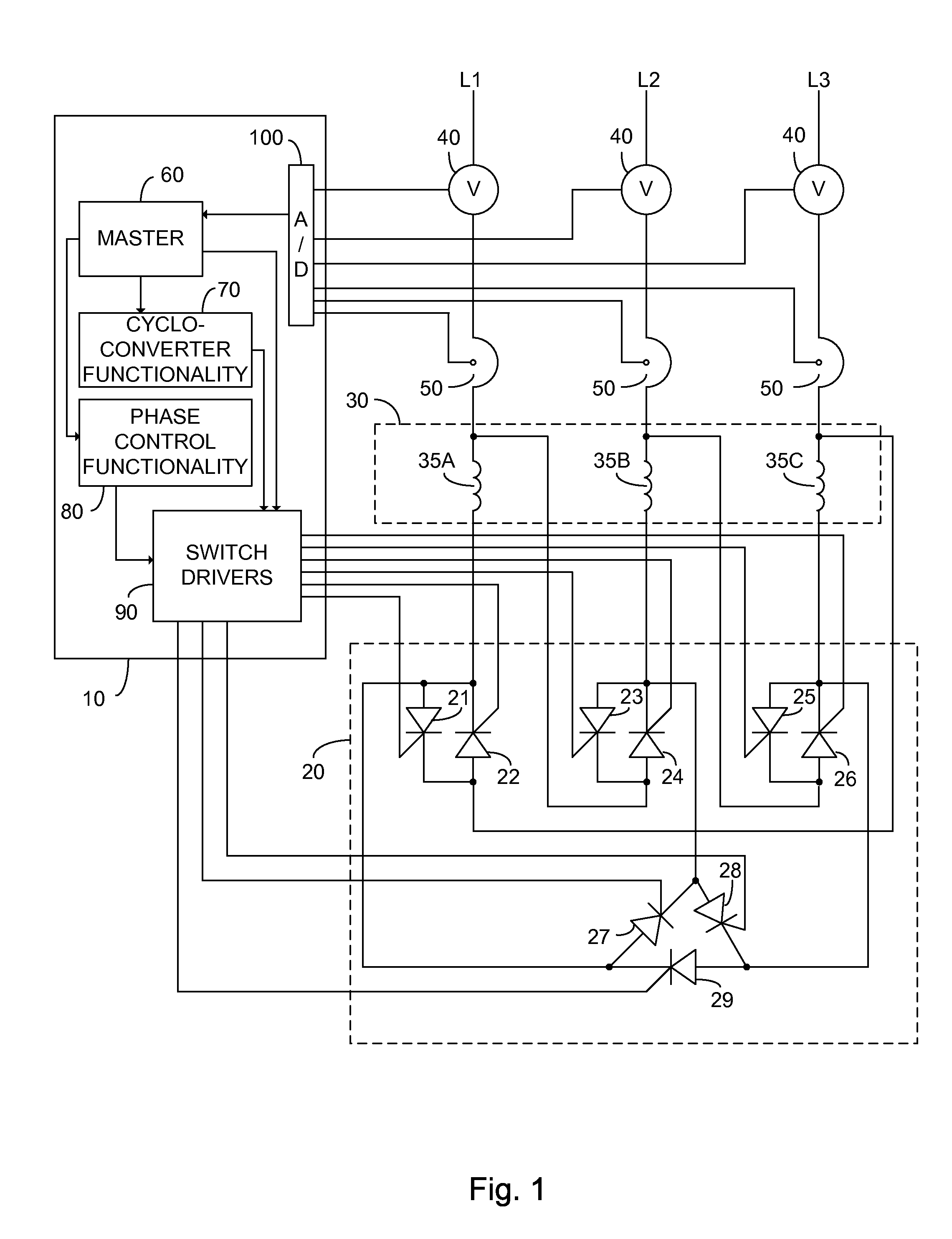
[0025]FIG. 1 illustrates a high level schematic diagram of a system comprising: a source of three phase electricity, the phases respectively denote L1, L2 and L3; an alternating current motor controller 10; a semiconductor switching unit 20 comprising a plurality of semiconductor switches, illustrated without limitation as thyristors, and denoted respectively thyristors 21, 22, 23, 24, 2526, 27, 28 and 29; an AC motor 30 constituted of at leas...


PUM


Abstract

An alternating current motor control system constituted of: a control unit; a cycloconverter functionality; a phase control functionality; and a semiconductor switching unit comprising a plurality of electronically controlled semiconductor switches each associated with a particular winding of a target alternating current motor and each independently responsive to the control unit. In one embodiment the semiconductor switching unit is arranged to connect the windings of the target alternating current motor to a three phase power input in one of a star and a delta configuration responsive to the control unit.

Description

TECHNICAL FIELD[0001]The invention relates generally to the field of alternating current motors, and in particular to a method and apparatus enabling low cost control of a three phase alternating current motor.BACKGROUND[0002]AC motors for industrial applications typically exhibit a plurality of windings and operate on three phases of electricity. Generally speaking the windings are arranged symmetrically and connected to the three phases of electricity either in a delta configuration or a star configuration, with the star configuration also known as a Wye configuration. In the delta configuration, the finish of each winding is connected to the start of the next winding. In the star configuration, one end of all of the three windings are connected together. The delta configuration exhibits an increased current through the motor windings as compared to the star configuration, and thus the star configuration is typically used for direct line connected motor start up so as to avoid pow...

Claims


Application Information

Patent Timeline
IPC IPC(8): H02P27/04H02P27/00
CPCH02P27/04
Inventor NAIMAN, ARTHUR
Owner ELSA CJSC
Learn More