Method and device for path switchover

a path switchover and path technology, applied in the field of communication, can solve the problems of not meeting the requirements of real-time services, the path and the transmission equipment themselves are unavoidable, and the signal attenuation of some extent caused by the path, so as to reduce the complaints of users and the degree of user satisfaction with the carrier, the effect of improving the satisfaction degree of users to the carrier

Active Publication Date: 2011-01-13
HUAWEI TECH CO LTD
View PDF5 Cites 94 Cited by
  • Summary
  • Abstract
  • Description
  • Claims
  • Application Information

AI Technical Summary

Benefits of technology

[0020]In the present disclosure, the method for switching the path may integrate the Network Quality Analysis (NQA) technology, detecting path signal quality, with the fast path switching technology of the TE FRR, and the detection value of the NQA technology may trigger the fast path switching of the TE FRR. When the signal quality of the path degrades, making the QoS requirement of the SLA hard to meet, by using the method provided in the present disclosure to deploy the network of the carrier, the traffic may be switched to standby path to meet the requirement of the SLA as originally agreed between the carrier and the user; as a result, the satisfactory degree of the user to the carrier is improved to effectively reduce the complaints from the user and the compensation claimed by the user.

Problems solved by technology

The conventional art, however, takes at least 3s to detect the fault of the adjacent devices and then trigger the TE FRR switching; as a result, this can not meet the requirement of the real-time services, such as speech, video, etc on the interruption interval; when the path and node devices work normally, and a fault occurs on a forwarding engines, ie on routers, where the fault is caused by a fault on the forwarding engines or internal errors, this fault can not be detected.
Since the carrier network, especially the massive carrier network, usually undergoes the long-distance transmission path; therefore, the signal attenuation of some extent caused by the path and the transmission equipment themselves is unavoidable.
Since many long-distance transmission paths adopt the original transmission paths or paths via the satellite and microwave, the signal quality and the QoS can not be guaranteed, either could the SLA signed by the user be satisfied, thereby degrading the user's experience and the satisfactory degree of the user to the carrier.
In the above solution, although it is guaranteed that the TE FRR is triggered after the fault is detected; when the quality of the signal degrades, for example, when the congestion caused by heavy traffic (especially, burst traffic for wide application of Peer to Peer (P2P), attack on network, equipment virus, etc) occurs in the path of the traffic of the voice and video real-time services, a great deal of packet loss may happen to the traffic of the voice and video real-time service or long delay may occur, thereby seriously degrading the QoS.
Under this condition, however, faults do not occur in the path and node that carry the traffic, and in the solution of the prior art, the TE FRR can not triggered; as a result, even though a light-load standby path is deployed in the conventional network, the TE FRR can not be triggered to switch to the standby path, thereby degrading the QoS and causing the waste of the path and bandwidth.

Method used


Image

  • Method and device for path switchover
  • Method and device for path switchover
  • Method and device for path switchover

Examples


embodiment 1

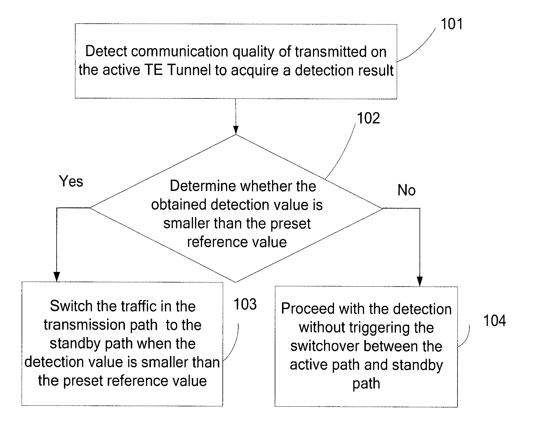
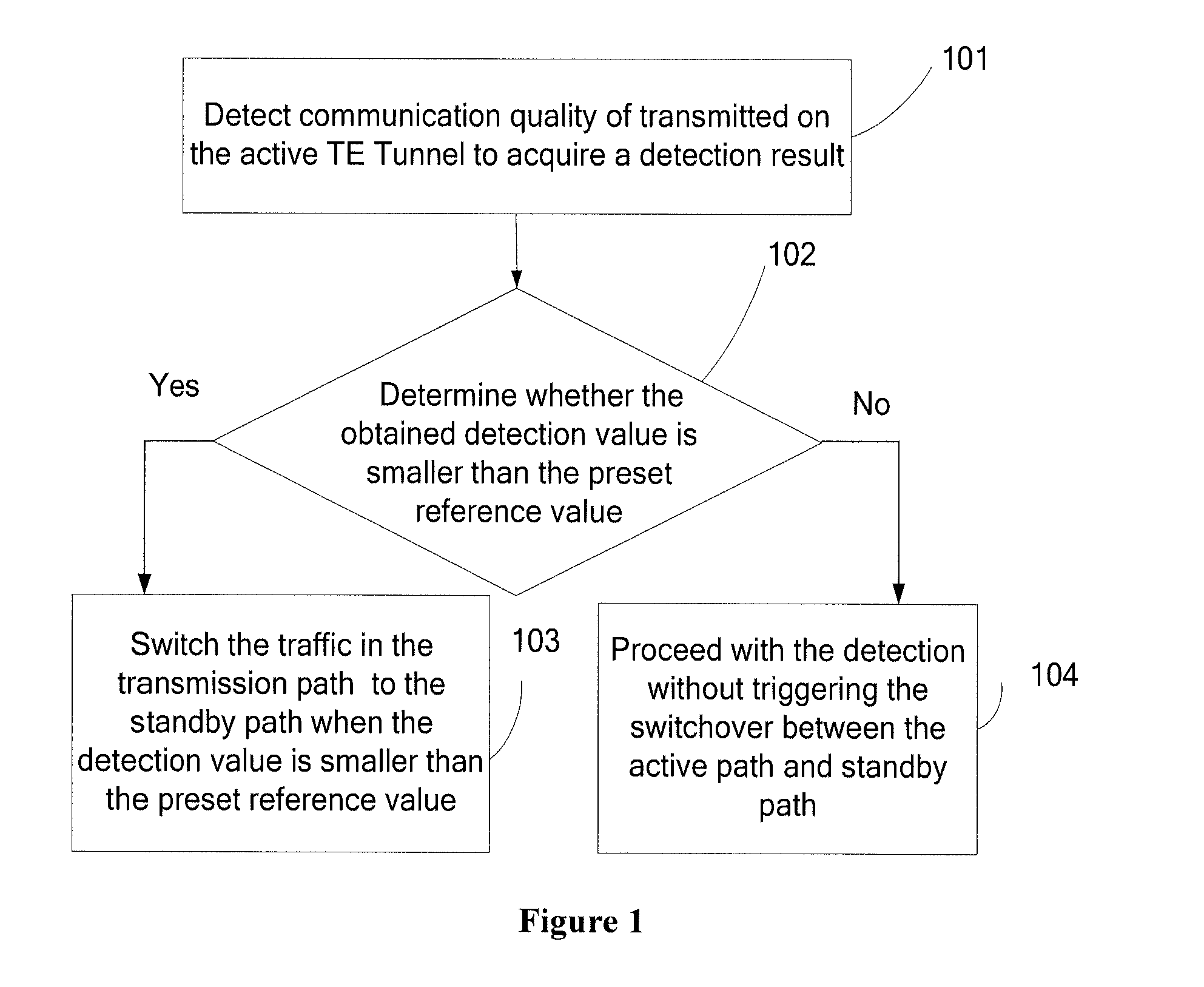
[0031]Referring to FIG. 1, the embodiment of present disclosure provides a method for path switchover; forwarding the traffic through the MPLS TE in the network is taken as an example, which is as follows:

[0032]101: Detect quality of a service traffic transmitted on the main TE Tunnel and acquire the detection result.

[0033]The detection on the QoS of the transmission path may be realized through NQA, and the NQA may detect the performances of various protocols running on the internet, so the operation indicators of various network services may be connected in real time; for example, the total delay of the HTTP, the TCP connection delay, the Domain Name System / Domain Name Service (DNS) parsing delay, the file transmission rate, the File Transfer Protocol (FTP) connection delay, or the DNS parsing error ratio. The NQA is also an effective tool for detecting and locating the network fault, thereby easily finding out the network problems. Namely, the NQA is an extension and enhancement ...

embodiment 2

[0045]On the basis of embodiment 1, in order to overcome the problem that the traffic switches from the active TE Tunnel to the standby TE Tunnel frequently due to the unstable path communication quality, a vibration suppression method is provided in an embodiment of the present disclosure to guarantee an optimal communication quality. The embodiment is as follows:

[0046]Firstly, the service traffic in the active TE Tunnel is detected to acquire a detection value.

[0047]Then four parameters of penalty value, Suppress, reuse and ceiling are set by using the method of vibration suppression. FIG. 3 is a diagram of the path vibration suppression. The TE Tunnel communication quality is set as the ceiling; the communication quality reference value is set as the Suppress, while a reuse of the communication quality is set as well. When the TE Tunnel communication quality is degraded and the Suppress is reached, and then the TE FRR is triggered to switch; then after a period of time, when the ...

embodiment 3

[0049]As shown in FIG. 4, the present disclosure provides a device for path switching and the device the following modules:

[0050]a detecting module, configured to detect communication quality of traffic, transmitted on the active path;

[0051]an obtaining module, configured to obtain the detection result according to the detection of the detecting module;

[0052]a determining module, configured to determine whether the detection result meets a switching condition according to the obtained detection result; and

[0053]a switching module, configured to switch the traffic transmitted on the active path to the standby path when the detection result is positive.

[0054]When the obtaining module obtains the detection result of the communication quality from the detecting module, the obtaining module may obtain one communication quality parameter or multiple communication quality parameters; for example, when NQA is adopted for detection, the NQA may detect whether the TCP, UDP, DHCP, FTP, HTTP, a...


PUM


Abstract

A method and device for path switchover in communications field are provided. The method includes: detecting communication quality of traffic transmitted on an active path and obtaining a detection value of the communication quality; determining whether the detection value meets a switching condition; if yes, switching the traffic transmitted on the active path to a standby path. The device includes a detecting module, an obtaining module, a determining module and a switching module. The embodiment of the present disclosure integrates the NQA technology for detecting the path communication quality and the TE FRR fast path switching technology, and the NQA detection result may trigger the TE FRR path to switch quickly. Therefore, when the signal quality of the path degrades, making the QoS requirement of the SLA hard to meet, the traffic may be switched to standby path to meet the requirement of the SLA agreed originally between the carrier and the user, so as to improve the user experience and the satisfactory degree on the service provided by the carriers.

Description

CROSS-REFERENCE TO RELATED APPLICATIONS[0001]This application is a continuation of International Application No. PCT / CN2009 / 071394, filed on Apr. 22, 2009, which claims priority to Chinese Patent Application No. 200810096168.1, filed on May 9, 2008, both of which are hereby incorporated by reference in their entireties.FIELD OF THE INVENTION[0002]This application relates to the communications field, in particular, to a method and device for path switchover.BACKGROUND OF THE INVENTION[0003]At present, the great development of communications technology accelerates the upgrading of the communications network; the security of the network, however, is the most fundamental performance criteria. For example, for the voice service, the switching time for end-to-end protection must be within 200 ms to meet the performance criteria. In order to meet various performance criteria, the IP bearer network brings into the device, path, network, etc Multi-Protocol Label Switching, Traffic Engineerin...

Claims


Application Information

Patent Timeline
Patent Type & Authority Applications(United States)
IPC IPC(8): H04L12/26H04L45/24H04L12/54H04L45/50
CPCH04L12/5695H04L45/02H04L45/026H04L47/745H04L45/308H04L47/728H04L45/22H04L47/70
Inventor BAI, LIANWEI
Owner HUAWEI TECH CO LTD
Why Eureka
Try Eureka