Atomic layer growing apparatus and thin film forming method

a growing apparatus and growing technology, applied in the direction of coatings, chemical vapor deposition coatings, plasma techniques, etc., can solve the problems of difficult stably generating plasma, low plasma density, degrading film quality, etc., to reduce the contamination of the substrate, enhance the deposition reaction activity of ald methods, and reduce the damage of plasma formed films

Inactive Publication Date: 2011-01-13
MITSUI ENG & SHIPBUILD CO LTD
View PDF0 Cites 14 Cited by
  • Summary
  • Abstract
  • Description
  • Claims
  • Application Information

AI Technical Summary

Benefits of technology

[0020]In view of the foregoing, an object of the invention is to provide an atomic layer growing apparatus that stably generates the high-density plasma to be able to enhance the reaction activity in the deposition using the atomic layer growing method, reduces the plasma damage of the formed film, and can reduce the contamination by the particle and a thin-film forming method.Means for Solving the Problems
[0043]According to the invention, by the use of the antenna array, the high-density plasma is stably generated, the neutral radical can substantially evenly be supplied to the large-area substrate, and the deposition reaction activity of the ALD method can be enhanced. The antenna array is disposed not above the substrate, but in a place away from the end portion of the substrate. Therefore, the plasma damage of the formed film is reduced, and the particles generated near the antenna array do not directly fall on the substrate, so that the contamination of the substrate can considerably be reduced.

Problems solved by technology

Accordingly, in the ALD method deposition in which the gas pressure becomes several pascals or more by the source gas supplied in a pulsing way, unfortunately it is difficult to stably generate plasma.
In the CCP, although there is no restriction of the gas pressure, unfortunately the plasma density is intrinsically low.
Like the ALD apparatus 50 illustrated in FIG. 7, when the antenna array 28 is disposed above the substrate 42, the formed film is damaged by the plasma, which causes a problem in that film quality is degraded.
Part of the film deposited on the surface of the antenna element 26 falls off, or dust or a reaction product (fine particle) produced in the gas phase becomes a particle, and there is a risk of contaminating the surface of the substrate 42 to degrade the film quality.

Method used


Image

  • Atomic layer growing apparatus and thin film forming method
  • Atomic layer growing apparatus and thin film forming method
  • Atomic layer growing apparatus and thin film forming method

Examples


Embodiment Construction

[0052]An atomic layer growing apparatus and a thin-film forming method according to an exemplary embodiment of the invention will be described in detail with reference to the drawings.

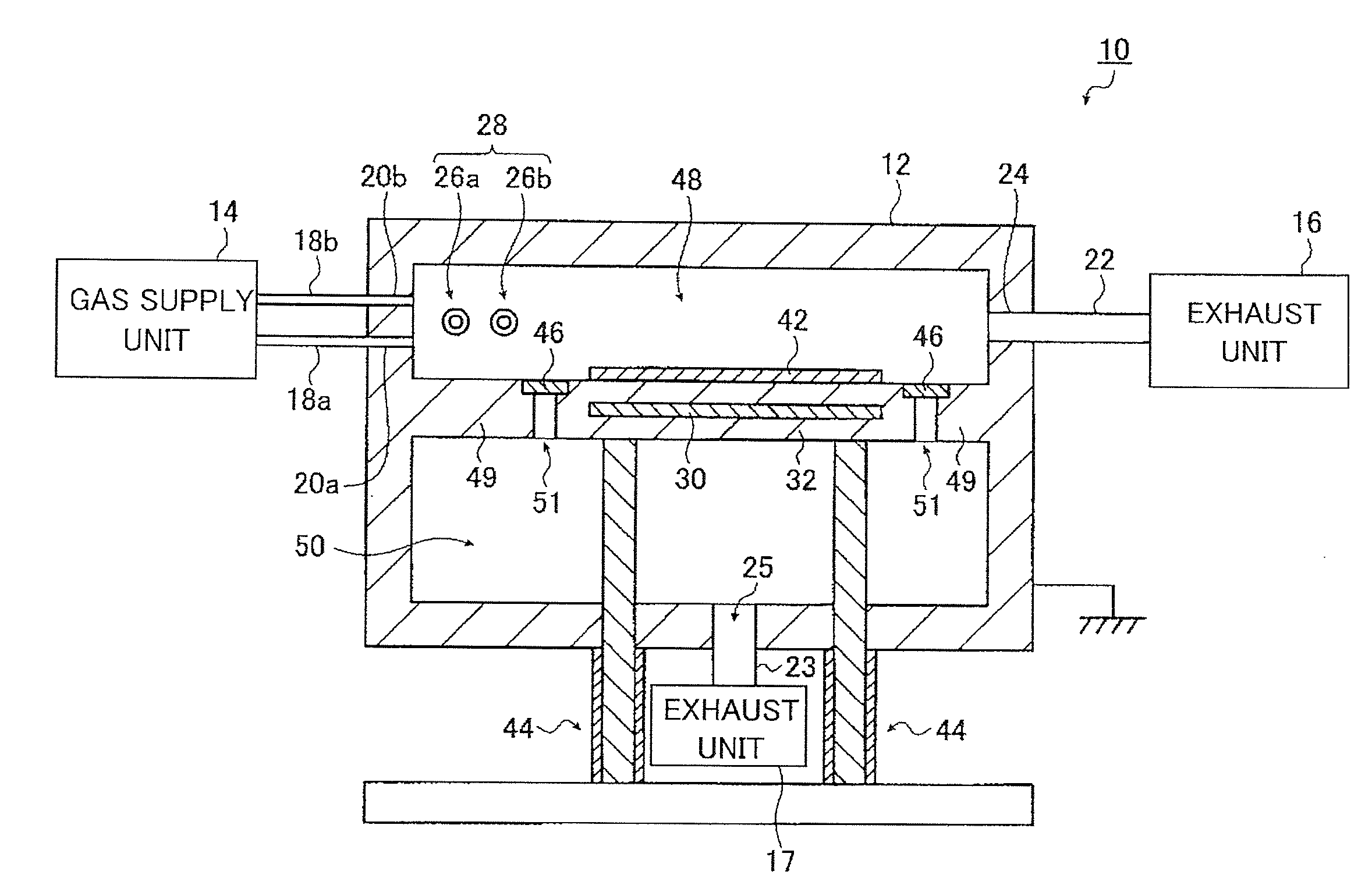
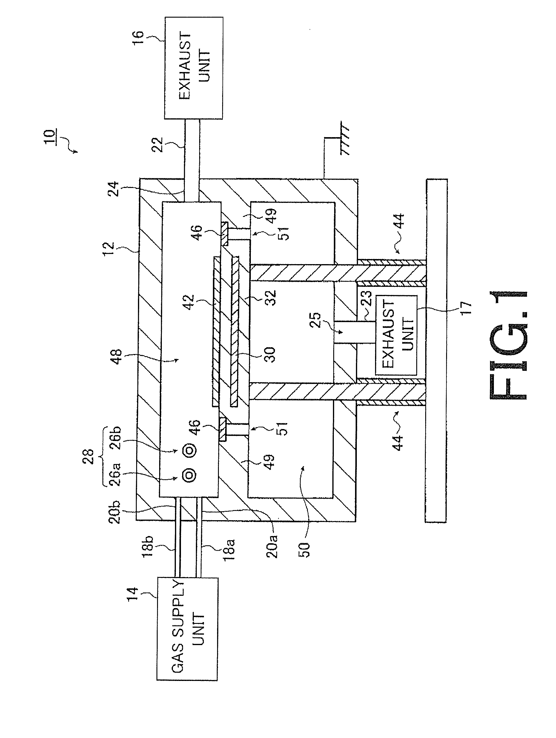
[0053]FIG. 1 is a schematic diagram illustrating a configuration of an ALD apparatus according to an embodiment of the invention. In an ALD apparatus 10 illustrated in FIG. 1, the ALD method is adopted, and two kinds of deposition gases (the source gas and the oxidizing gas or nitriding gas) composed mostly of elements constituting the film to be formed are alternately supplied onto the deposition target substrate. At this point, the plasma is generated in order to enhance the reaction activity, and the oxide film or nitride film of the source gas is formed in an atomic layer or a few atomic layers on the substrate. Assuming that one cycle is the above-described processing, the film having a desired thickness is formed by repeating the processing cycle plural times.

[0054]The ALD apparatus 10 includes a...


PUM

PropertyMeasurementUnit
temperatureaaaaaaaaaa
pressureaaaaaaaaaa
frequencyaaaaaaaaaa

Abstract

An atomic layer growing apparatus includes a deposition container, a gas supply unit, and an exhaust unit. In the deposition container, an antenna array and a substrate stage are provided. The antenna array is formed by disposing a plurality of antenna elements in parallel, each of the antenna elements being configured by coating a rod-shaped antenna body with a dielectric material. The antenna array generates plasma using one of an oxidizing gas and a nitriding gas. The substrate is placed on the substrate stage. The gas supply unit alternately supplies the source gas and the oxidizing gas toward the substrate stage from a supply hole made in a sidewall of the deposition container when a film is formed on the substrate. The exhaust unit exhausts the source gas and one of the oxidizing gas and the nitriding gas, which are alternately supplied into the deposition container.

Description

TECHNICAL FIELD[0001]The present invention relates to an atomic layer growing (hereinafter also abbreviated to ALD (Atomic Layer Deposition)) apparatus that forms a thin film in atomic layer units on a substrate and a thin-film forming method.BACKGROUND ART[0002]In the ALD method that is one of thin-film forming techniques, two kinds of gases composed mostly of elements constituting a film to be formed are alternately supplied onto a deposition target substrate, and formation of a thin film in an atomic layer or a few atomic layers is repeated plural times on the substrate, thereby forming a film having a desired thickness. For example, a source gas containing Si and an oxidizing gas containing O are used when a SiO2 film is formed on the substrate. A nitriding gas is used instead of the oxidizing gas when a nitride film is formed on the substrate.[0003]In the ALD method, while the source gas is supplied, a source gas component only for one or several layers is adsorbed to a substra...

Claims


Application Information

Patent Timeline
Patent Type & Authority Applications(United States)
IPC IPC(8): C23C16/509C23C16/00
CPCC23C16/403C23C16/45536H01L21/3141H01J37/3211H01J37/321H01L21/02274H01L21/0228H01L21/02205H01L21/02178
Inventor MURATA, KAZUTOSHIWASHIO, KEISUKE
Owner MITSUI ENG & SHIPBUILD CO LTD
Why Eureka
Try Eureka