Method for Removal of Entrained Gas in a Combined Cycle Power Generation System

a power generation system and combined cycle technology, applied in the field of power systems, can solve problems such as system shutdown, undesirable thermal loss, and loss of vacuum

Inactive Publication Date: 2011-01-20
SIEMENS AG
View PDF6 Cites 19 Cited by
  • Summary
  • Abstract
  • Description
  • Claims
  • Application Information

AI Technical Summary

Problems solved by technology

For example, the steam cycle condenser is normally maintained under a partial vacuum, but when the system is shut down the vacuum is lost.
A method for removing carbon dioxide from the working fluid is to simply vent the fluid, but this can require exhausting relatively large amounts of the hot fluid, resulting in undesirable thermal losse

Method used


Image

  • Method for Removal of Entrained Gas in a Combined Cycle Power Generation System
  • Method for Removal of Entrained Gas in a Combined Cycle Power Generation System

Examples


Embodiment Construction

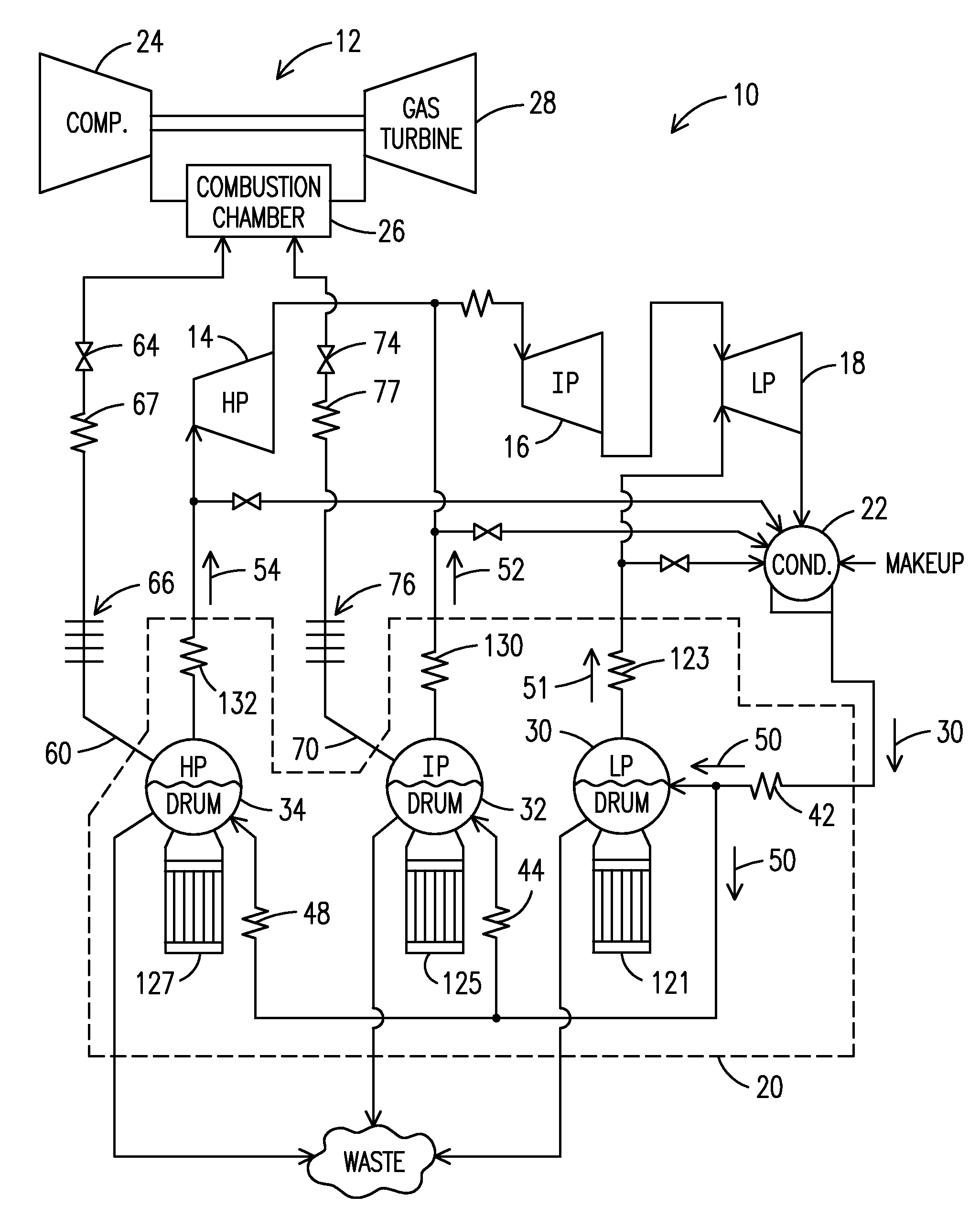
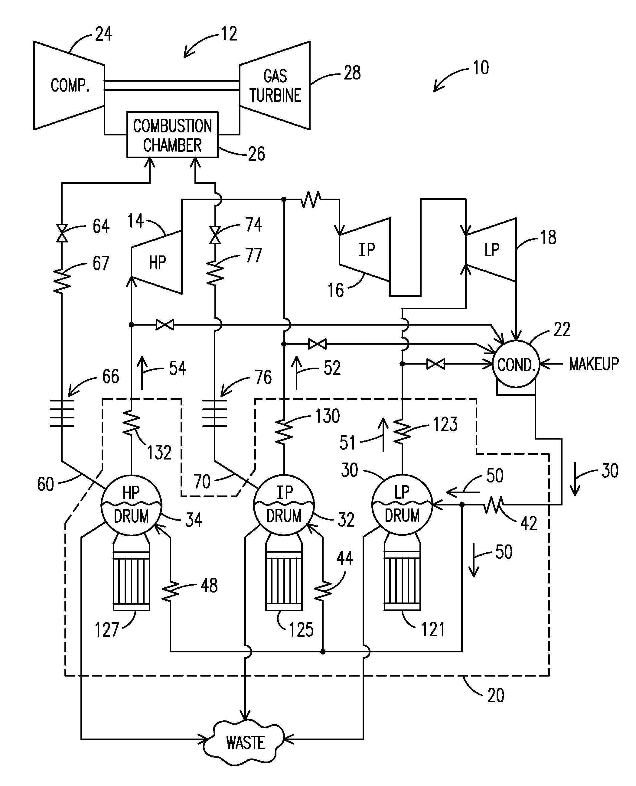
[0008]The FIGURE illustrates a simplified example embodiment of a combined cycle system 10 formed with a combustion turbine system 12, a high pressure steam turbine 14, an intermediate pressure steam turbine 16, a low pressure steam turbine 18, a Heat Recovery Steam Generator (HRSG) 20 (shown with phantom lines), and a condenser 22 coupled to receive working fluid from the low pressure steam turbine 18. The combustion turbine system 12 comprises an air compressor section 24, a combustion chamber 26 and a gas turbine 28 which are shown schematically. Other conventional components and fluid flow lines are omitted for clarity. For example, it is to be understood that a fluid flow line connects the exhaust output of the turbine 28 to an input at the high temperature side of the HSRG 20. Generally a combined cycle system in accord with the invention may comprise multiple low, intermediate and high pressure steam turbines, multiple gas turbines and multiple HRSGs.

[0009]Exhaust (not shown)...


PUM


Abstract

A combined cycle power generation system (10) includes a steam turbine (14, 16, 18), a combustion system (12) including a compressor (24), a combustion chamber (26), a gas turbine (28), and a HRSG (20) to generate steam with energy from the combustion turbine. A flow line (60, 70) passes superheated steam into the combustion chamber. In an associated method a first source of power is provided via a combustion process having a variable reaction temperature in a first turbine. A second source of power is provided via a second turbine. Components of the system are placed in a mode of increasing power output with steam generated from the HRSG, during which a portion of the steam is provided into a combustion chamber associated with operation of the second turbine.

Description

FIELD OF THE INVENTION[0001]The present invention relates generally to power systems and, more particularly, to combined cycle power generation systems of the type incorporating both a Rankine cycle and a combustion process. More specifically, the invention relates to a systems and methods for reducing the levels of undesirable gaseous materials present in such combined cycle power generation systems.BACKGROUND OF THE INVENTION[0002]Combined cycle power plants have come into widespread use because they incorporate heat exchangers that can recover heat from the hot gas exhaust stream of a combustion engine. Conventionally the recovered heat is used to generate the working fluid of a steam turbine. This results in more efficient power generation than is achievable with only a combustion turbine or only a steam turbine. See, for example, U.S. Pat. No. 5,375,410 which is assigned to the assignee of the present invention and incorporated herein by reference.[0003]Generally, combined cycl...

Claims


Application Information

Patent Timeline
IPC IPC(8): F02C6/00F02G3/00F02C7/08
CPCF01K13/02F01K21/047F01K23/106F02C3/30F22B37/22F05D2270/082F22G1/165Y02E20/16F02C6/18
Inventor BELLOWS, JAMES C.
Owner SIEMENS AG
Why Eureka
Try Eureka