
Helical Tube Bundle Arrangements for Heat Exchangers

a heat exchanger and bundle arrangement technology, applied in the field of shellandtube heat exchangers, can solve the problems of limiting the use of these systems in marine applications, contributing to the capital cost of otec plants, and high capital cost of these systems,

Active Publication Date: 2011-01-20
LOCKHEED MARTIN CORP
View PDF23 Cites 38 Cited by
  • Summary
  • Abstract
  • Description
  • Claims
  • Application Information

AI Technical Summary

Benefits of technology

The present invention provides a heat exchanger that is cost-effective and suitable for use in various applications such as OTEC systems, nuclear reactors, and chemical plants. The heat exchanger has a unique design with multiple tube bundles arranged close-packed at each tube sheet, which allows for efficient heat transfer and reduced fouling. The tubes are mechanically coupled to prevent any motion relative to each other, which further improves heat transfer and reduces fouling. The heat exchanger also includes a first and second tube bundle enclosed in separate shrouds for conveying different fluids. Overall, the heat exchanger has improved performance and durability with reduced maintenance costs.

Problems solved by technology

OTEC systems have been shown to be technically viable, but the high capital cost of these systems has thwarted commercialization.
The heat exchangers are the second largest contributor to OTEC plant capital cost (the largest is the cost of the offshore moored vessel or platform).
Unfortunately, shell-and-tube heat exchangers have several drawbacks that have thus-far limited their use in marine applications.
Heat transfer efficiency is limited by, among other things (1) baffles that are typically included in the pressure-vessel to induce turbulence and transverse flow of the second fluid, and (2) a limitation on the flow rate of the second fluid to avoid inducing vibration and flow forces that induce mechanical stresses and strains on the tubes.
A second drawback of conventional shell-and-tube heat exchangers is that they are prone to “bio-fouling.” Bio-fouling decreases efficiency and leads to increased maintenance costs (particularly for heat exchangers located at deep-water levels).
A third drawback of conventional shell-and-tube heat exchangers is that they are not well-suited to seawater applications, such as OTEC.
Since the tubes are press fit or fusion-welded into the tube sheets, it is difficult to ensure fluidic isolation between the primary fluid inside the tubes and seawater flowing around the tubes through the shell.
Further, the reliability of conventional shell-and-tube heat exchangers is compromised by galvanic corrosion that occurs at the welded joints used to seal the tubes to the tube sheets.
Galvanic corrosion occurs due to reactivity between dissimilar metals included in fusion welds.
Reliability is degraded further by the potential for crevice corrosion in regions of stagnant flow even for shell-and-tube designs customized for OTEC applications.
Historically, these drawbacks have driven the size and cost for shell-and-tube heat exchangers too high for practical consideration.
But development of a low-cost OTEC heat exchanger having high heat-exchange capacity, high flow rates, low pumping parasitic losses, and long life in the ocean environment remains elusive.

Method used


Image

  • Helical Tube Bundle Arrangements for Heat Exchangers
  • Helical Tube Bundle Arrangements for Heat Exchangers
  • Helical Tube Bundle Arrangements for Heat Exchangers

Examples


Embodiment Construction

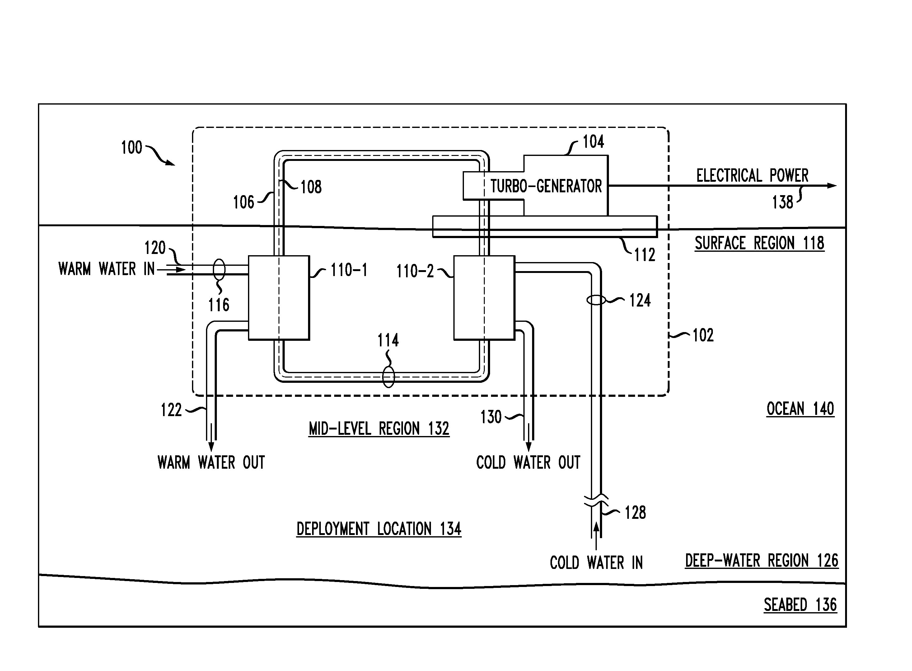
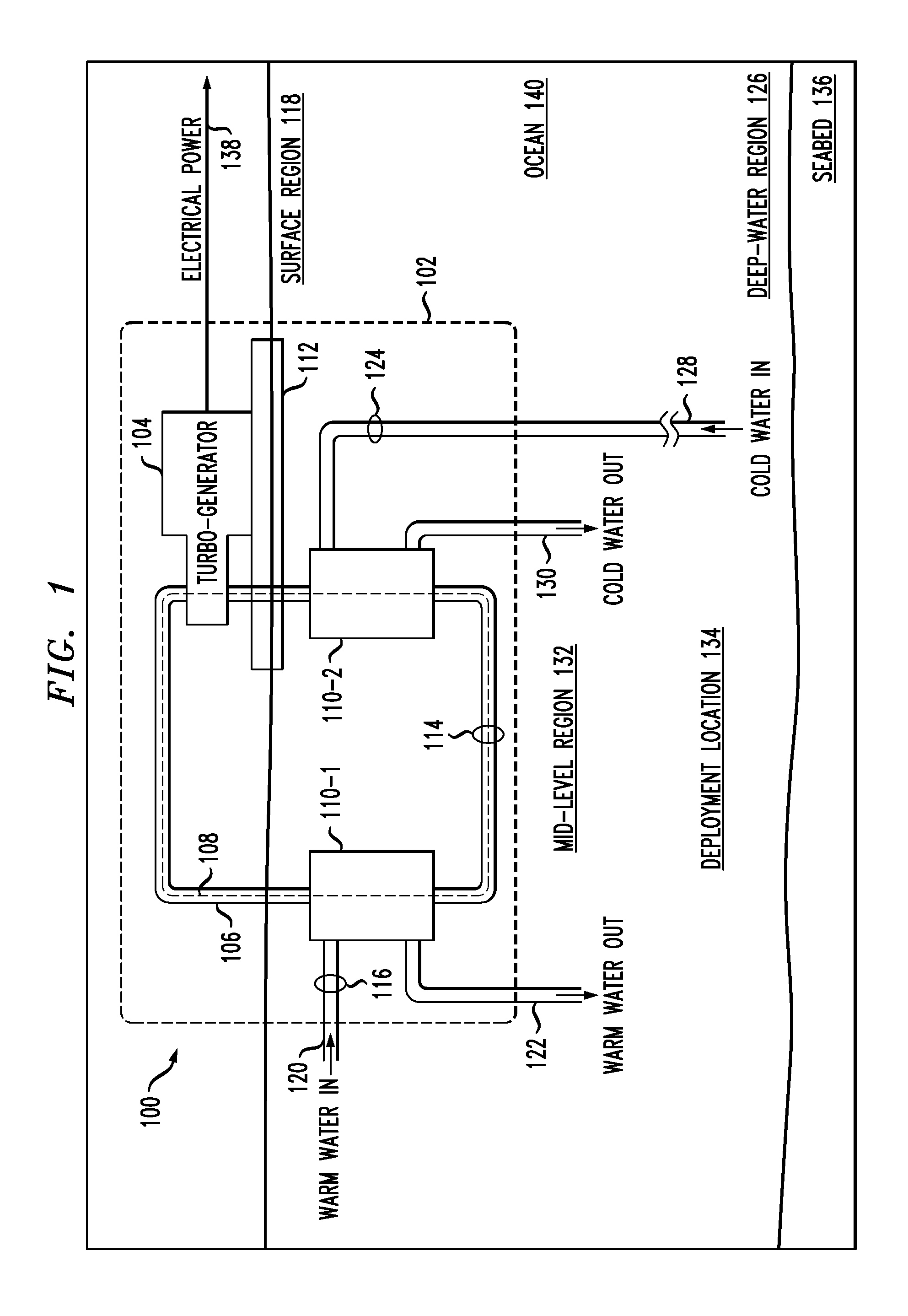
[0032]FIG. 1 depicts a schematic diagram of an OTEC power generation system in accordance with an illustrative embodiment of the present invention. OTEC system 100 comprises offshore platform 102, turbogenerator 104, closed-loop conduit 106, evaporator 110-1, condenser 110-2, hull 112, pumps 114, 116, and 124, and conduits 120, 122, 128, and 130.

[0033]Offshore platform 102 is a tension leg offshore platform comprising buoyant hull 112, which includes a deck, caissons, and pontoons. The hull is supported above seabed 136 by rigid tension legs that are anchored to seabed 136 at deployment location 134. For clarity, the deck, caisson, pontoons, and tension legs are not shown in FIG. 1.

[0034]In some embodiments, offshore platform 102 is deployed at a deployment location in a body of water other than an ocean (e.g., a lake, sea, etc.). In some embodiments, offshore platform 102 is an offshore platform other than a tension leg offshore platform, such as a semi-submersible, spar, drill shi...


PUM


Abstract

A heat exchanger comprising helically wound tube bundles is disclosed. The helically wound tube bundles are joined with tube sheets to define a primary working fluid system that is fluidically isolated from a secondary working fluid system. The tube sheets and tubes are formed of the same material, which facilitates their joining by means of joints that are substantially galvanic corrosion-resistant joints.

Description

CROSS REFERENCE TO RELATED APPLICATIONS[0001]moon This case claims priority of U.S. Provisional Patent Application Ser. No. 61 / 225,991, which was filed Jul. 16, 2009 (Attorney Docket: 711-283US), and which is incorporated herein by reference.[0002]If there are any contradictions or inconsistencies in language between this application and one or more of the cases that have been incorporated by reference that might affect the interpretation of the claims in this case, the claims in this case should be interpreted to be consistent with the language in this case.FIELD OF THE INVENTION[0003]The present invention relates to heat exchangers in general, and, more particularly, to shell-and-tube heat exchangers.BACKGROUND OF THE INVENTION[0004]Ocean thermal energy conversion (“OTEC”) is a method for generating electricity based on the temperature difference that exists between deep and shallow waters of a large body of water, such as an ocean, sea, gulf, or large, deep lake. An OTEC system u...

Claims


Application Information

Patent Timeline
Patent Type & Authority Applications(United States)
IPC IPC(8): F28F1/10
CPCF28D7/024F28F9/013F28F9/18F28F2009/226F28F21/084F28F2275/062Y02E10/34F28F19/00Y02E10/30F28D7/02F28D7/022F28F1/10F28F1/105
Inventor NAGURNY, NICHOLAS J.LEVINGS, NATALIE B.BECKNER, DEREK M.MAURER, SCOTT M.
Owner LOCKHEED MARTIN CORP
Learn More