Control unit and method for activating personal protection devices

a technology of personal protection device and control unit, which is applied in the direction of pedestrian/occupant safety arrangement, vehicular safety arrangement, transportation and packaging, etc., can solve the problems of premature termination of on state, and achieve quick energy storage, low input current, and low load capacity

Active Publication Date: 2011-01-20
ROBERT BOSCH GMBH
View PDF2 Cites 8 Cited by
  • Summary
  • Abstract
  • Description
  • Claims
  • Application Information

AI Technical Summary

Benefits of technology

[0003]A control unit and method according to the present invention for triggering a personal protection device may have an advantage that the charging rate, i.e., how quickly the energy storage device with which with the energy reservoir is charged, is controlled by a signal generated outside and / or inside the charging circuit. In addition to open-loop control, closed-loop regulation is also possible. Requirements in terms of charging rate can thereby be met. It is possible in particular for smaller personal protection systems, for which only a portion of the maximum performance of the charging circuit is sufficient, also to utilize only a portion of that performance, and thereby to exhibit a lower input current to the control unit in the energy reservoir charging phase. External components having a lower load capacity can be selected as a result, contributing to a cost reduction.

Problems solved by technology

In addition, a current monitor is active in the switching converter, which monitor can prematurely terminate the ON state, deviating from the fixed pulse duty factor, if the current monitoring limit value is reached.
In addition, a current monitor is active in the switching converter, which monitor can prematurely terminate the ON state, deviating from the regulated pulse duty factor, if the current monitoring limit value is reached.

Method used


Image

  • Control unit and method for activating personal protection devices
  • Control unit and method for activating personal protection devices
  • Control unit and method for activating personal protection devices

Examples


Embodiment Construction

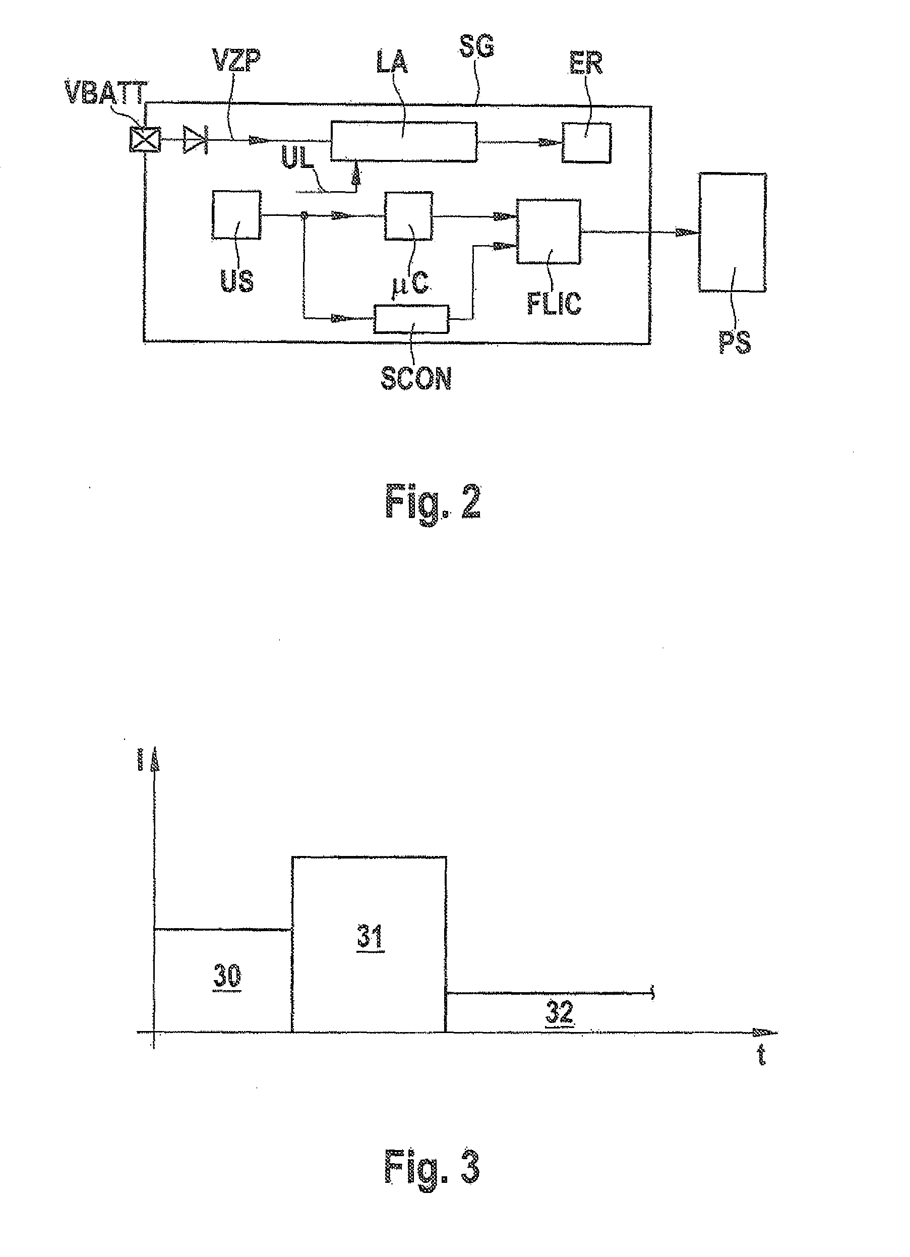
[0028]FIG. 2 shows an example control unit SG according to the present invention in a block diagram, only the components needed for an understanding of the present invention being depicted. Control unit SG controls personal protection devices PS, such as airbags or belt tighteners, as a function of signals of an accident sensor suite US that are evaluated by a microcontroller μC constituting an evaluation circuit; as a function of an initiation decision, microcontroller μC triggers a triggering circuit FLIC so that the personal protection devices are activated by this triggering circuit FLIC. In accordance with safety requirements for control units for triggering personal protection devices, the FLICs are authorized to activate personal protection devices PS only if a second microcontroller or a so-called safety controller (=SCON) confirms the triggering decision or arrives at the same decision. Triggering circuit FLIC uses the ignition energy for personal protection devices PS from...


PUM


Abstract

A control unit and a method for triggering personal protection devices are proposed, which charge an energy reservoir for the control unit via a charging circuit. The charging circuit sets a charging rate for charging as a function of a signal generated outside the charging surface.

Description

FIELD OF THE INVENTION[0001]The present invention relates to a control unit and a method for triggering personal protection devices.BACKGROUND INFORMATION[0002]German Patent Application No. DE 10 2004 057 690 A1 describes a charging circuit for a control unit for triggering personal protection devices. This charging circuit serves to charge an electrical energy storage device that is embodied as a capacitor.SUMMARY[0003]A control unit and method according to the present invention for triggering a personal protection device may have an advantage that the charging rate, i.e., how quickly the energy storage device with which with the energy reservoir is charged, is controlled by a signal generated outside and / or inside the charging circuit. In addition to open-loop control, closed-loop regulation is also possible. Requirements in terms of charging rate can thereby be met. It is possible in particular for smaller personal protection systems, for which only a portion of the maximum perfo...

Claims


Application Information

Patent Timeline
Patent Type & Authority Applications(United States)
IPC IPC(8): H02J7/00
CPCB60R21/017
Inventor SCHUMACHER, HARTMUT
Owner ROBERT BOSCH GMBH
Why Eureka
Try Eureka