DC-DC Converter And Its Controlling Method

a technology of dc-dc converter and control method, which is applied in the direction of electric variable regulation, process and machine control, instruments, etc., can solve the problems of large device dimension, difficult to achieve high frequency implementation, and huge loss of main switching elements, etc., to achieve high frequency, reduce the effect of downsizing and large capacity

Inactive Publication Date: 2011-01-20
HITACHI LTD
View PDF3 Cites 32 Cited by
  • Summary
  • Abstract
  • Description
  • Claims
  • Application Information

AI Technical Summary

Benefits of technology

[0014]Also, it is another object of the present invention to provide a DC-DC converter for allowing a reduction in the dimension / weight of auxiliary inductors, and allowing implementation of the large capacity, the auxiliary inductors being designed for implementing a secure soft switching over a wide voltage control range.
[0015]In the present invention, its one aspect is as follows: A buck converter circuit and a boost converter circuit, which co-use a main inductor, are connected in series with each other between a DC power-supply and a DC load. Moreover, utilizing energy accumulated into first and second auxiliary inductors which are magnetically coupled to the main inductor, a current is flown through diodes during a short time-period including a point-in-time at which main switching elements of the buck and boost converter circuits are to be turned ON. Here, the diodes are connected in inversely parallel to the main switching elements.
[0019]Also, in a preferred embodiment of the present invention, there is further provided a control unit for turning ON the first and second auxiliary switching elements during a short time-period including a point-in-time at which the corresponding first and second main switching elements are to be turned ON, and flowing a forward-direction current through the corresponding first and second inversely-parallel diodes.
[0020]According to a preferred embodiment of the present invention, it becomes possible to implement a secure soft switching in a wide voltage control range ranging from an area lower than a DC power-supply voltage to an area higher than the DC power-supply voltage, and to implement a unidirectional DC-DC converter for allowing implementation of the high frequency and downsizing.
[0021]Also, according to a preferred embodiment of the present invention, a loosely-coupled transformer is used, thereby utilizing the leakage inductance positively. This feature makes it possible to provide a unidirectional DC-DC converter for allowing implementation of the soft switching in a more downsized manner.
[0022]Moreover, according to a preferred embodiment of the present invention, it becomes possible to provide a DC-DC converter for allowing implementation of the large capacity by optimally controlling continuous mode and discontinuous mode of a power-supply current.

Problems solved by technology

By the way, if no modification is made to the main circuit of the unidirectional DC-DC converter which is disclosed in Grover Victor Torrico Bascope, “Single-Phase High Power Factor Variable Output Voltage Rectifier, Using the Buck+Boost Converter: Control Aspects, Design and Experimentation”, switching losses in the main switching elements are tremendous in amount.
As a result, there exists a drawback that the implementation of high frequency is difficult to achieve, and that the device dimension becomes large.
Namely, in the boost converter circuits disclosed in JP-A-2005-318766 and JP-A-2006-14454, there exists a drawback that no control cannot be exerted over the output voltages which are lower than the DC power-supply voltage.
IA, Vol. 125, No. 11, 2005, and JP-A-6-311738, there exists a drawback that no control cannot be exerted over the output voltages which are higher than the DC power-supply voltage.
As a result, there exists a drawback that dimension / weight of the auxiliary inductors become increased.
Moreover, in JP-A-2006-14454, there also exists a drawback that, from the use of the transformer and its relationship with the circuit configuration, occurrence of voltage surge is feared due to influences of leakage inductance.

Method used


Image

  • DC-DC Converter And Its Controlling Method
  • DC-DC Converter And Its Controlling Method
  • DC-DC Converter And Its Controlling Method

Examples


1st embodiment

[0034]First, referring to FIG. 1 and FIG. 2, the explanation will be given below concerning a first embodiment of the present invention.

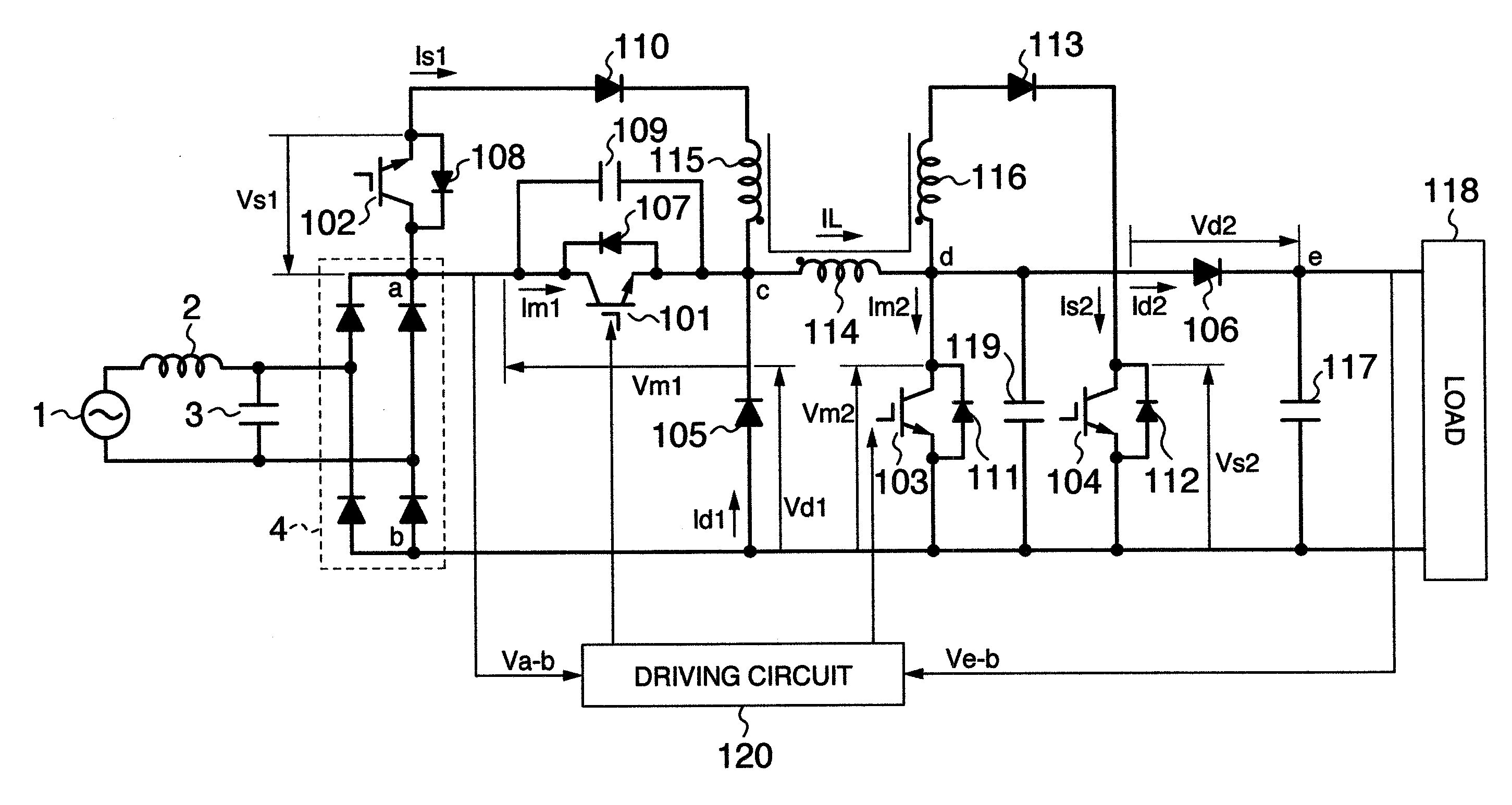
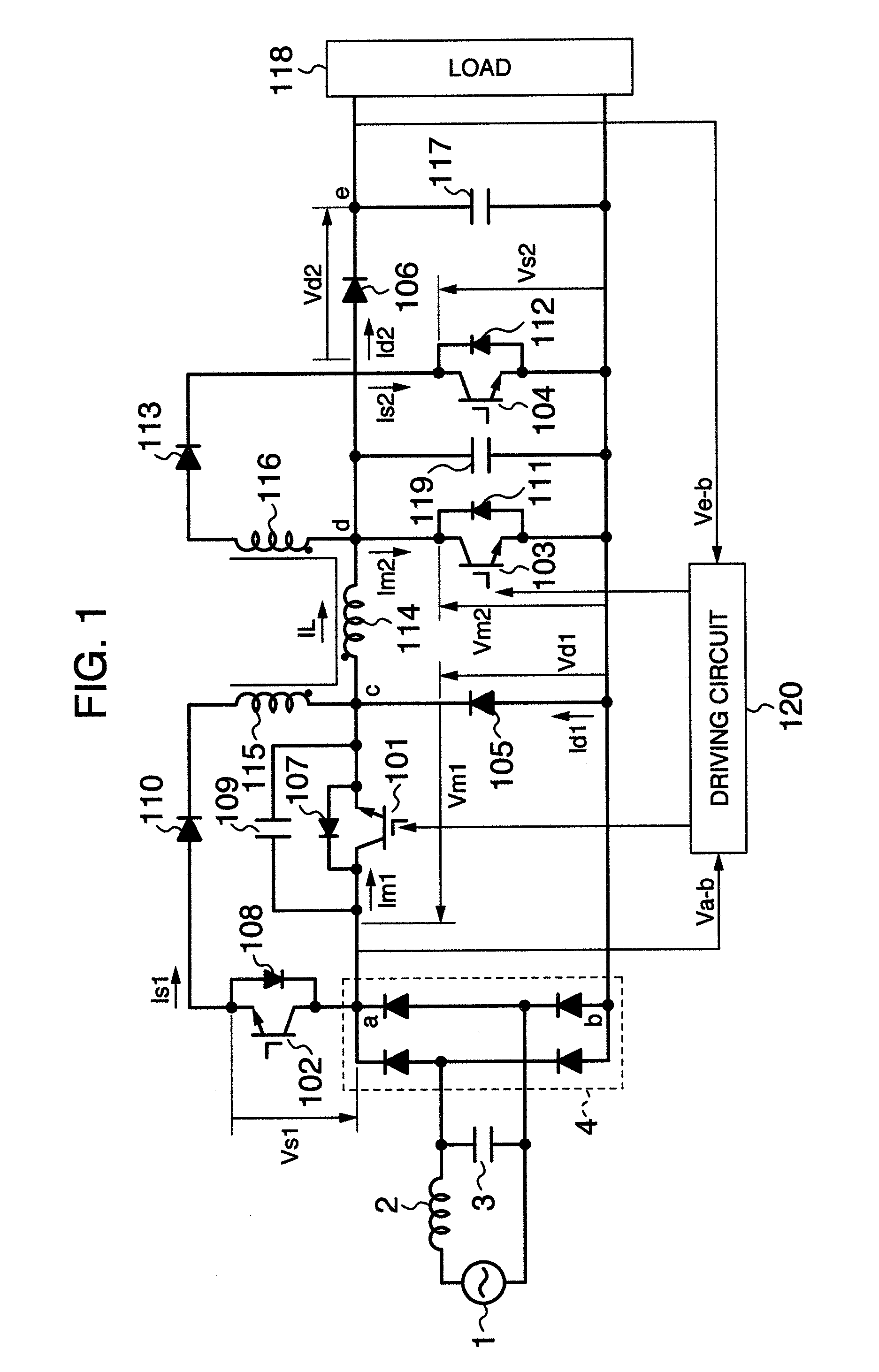
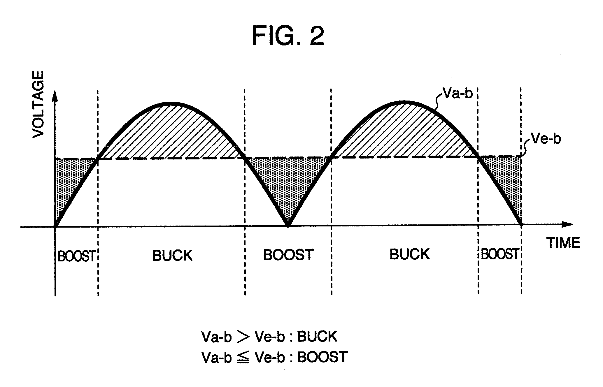
[0035]FIG. 1 is a configuration diagram of the main circuit of a unidirectional DC-DC converter according to the first embodiment of the present invention. The present embodiment is a unidirectional DC-DC converter of buck-boost type for allowing implementation of both a boost operation for outputting a voltage higher than an inputted voltage and a buck operation for outputting a voltage lower than the inputted voltage.

[0036]Explaining the main-circuit configuration in FIG. 1, a DC power-supply is configured with a commercial AC power-supply 1, a filter circuit including an inductor 2 and a capacitor 3, and a rectifier circuit 4. Namely, the entire AC voltage from the commercial AC power-supply 1 is rectified by the rectifier circuit 4 via the filter circuit including the inductor 2 and the capacitor 3, thereby being converted into a smooth DC volta...

2nd embodiment

[0068]Next, referring to FIG. 7 and FIG. 8, the explanation will be given below concerning a second embodiment of the present invention.

[0069]FIG. 7 is a configuration diagram of the main circuit of a unidirectional DC-DC converter according to the second embodiment of the present invention. The present embodiment is a unidirectional DC-DC converter of buck-boost type for allowing implementation of both the boost operation for outputting a voltage higher than an inputted voltage and the buck operation for outputting a voltage lower than the inputted voltage.

[0070]In FIG. 8, the same reference numerals are affixed to the same configuration components as the ones illustrated in FIG. 1, and thus the overlapped explanation will be avoided.

[0071]The point in which the present embodiment differs from the first embodiment is a driving method for driving the main IGBT 101, i.e., the first main switching element. The configuration of this driving method is as follows: A point-in-time at whic...

3rd embodiment

[0076]Next, referring to FIG. 9 and FIG. 10, the explanation will be given below concerning a third embodiment of the present invention.

[0077]FIG. 9 is a configuration diagram of the main circuit of a unidirectional DC-DC converter according to the third embodiment of the present invention. The present embodiment is a unidirectional DC-DC converter of buck-boost type for allowing implementation of both the boost operation for outputting a voltage higher than an inputted voltage and the buck operation for outputting a voltage lower than the inputted voltage.

[0078]In FIG. 9, the same reference numerals are affixed to the same configuration components as the ones illustrated in FIG. 1, and thus the overlapped explanation will be avoided.

[0079]The point in which the present embodiment differs from the first embodiment is a driving method for driving the main IGBT 101, i.e., the first main switching element. The configuration of this driving method is as follows: A point-in-time is detec...


PUM


Abstract

A unidirectional DC-DC converter and method of control thereof. The converter includes a DC power-supply, a buck converter circuit having a first main switching element, a boost converter circuit having a second main switching element, a first snubber capacitor, a first inversely-parallel diode, a control device, and an output diode.

Description

CROSS REFERENCE TO RELATED APPLICATION[0001]This application is a continuation of U.S. application Ser. No. 11 / 876,826, filed Oct. 23, 2007, the contents of which are incorporated herein by reference.BACKGROUND OF THE INVENTION[0002]The present invention relates to a unidirectional DC-DC converter for converting an inputted DC voltage into a DC voltage of different magnitude, and a controlling method therefor.[0003]In a buck-boost DC-DC converter for outputting an inputted DC voltage such that this inputted DC voltage is converted into a DC voltage of desired magnitude, implementation of high efficiency in this converter is made possible by lowering the switching loss with the use of soft switching technology. In accompaniment with this implementation, passive elements, such as inductor and capacitor, can be downsized by achieving implementation of high frequency in the driving frequency for switching elements.[0004]In Grover Victor Torrico Bascope, “Single-Phase High Power Factor V...

Claims


Application Information

Patent Timeline
Patent Type & Authority Applications(United States)
IPC IPC(8): H02M7/06G05F1/46
CPCH02M1/4208Y02B70/126H02M3/1582Y02B70/10
Inventor URUNO, JUNPEISHOJI, HIROYUKIKAMINAGA, YASUOKANOUDA, AKIHIKO
Owner HITACHI LTD
Why Eureka
Try Eureka