Method of mixing

a technology of mixing vessel and mixing chamber, which is applied in the field of mixing, can solve the problems of none of the priors

Active Publication Date: 2011-01-20
SARTORIUS STEDIM BIOTECH GMBH
View PDF15 Cites 72 Cited by
  • Summary
  • Abstract
  • Description
  • Claims
  • Application Information

AI Technical Summary

Benefits of technology

[0019]In a preferred embodiment, packing for shipping and storage may be improved through the use of a sectioned, foldable or telescopic shaft, thus reducing the size of the mixing vessel prior to use. Such an embodiment is especially preferred when the mixing vessel is intended for large volume applications.
[0021]It was a surprise to find that the flexible container can be operated up to volumes of more than 100 liters without separate outer stabilizing apparatuses. The reason for this is the double mounting of both ends of the central shaft on both a first and a second flange. Moreover, this construction makes it possible to mix media with higher density and viscosity. This is particularly advantageous when using the mixing container as a bioreactor. It was found that intensive stirring could be maintained even toward the end of a cultivation procedure, where the cell density has very much increased. In a preferred refinement, this construction makes it possible to operate the central shaft using a plurality of mixing elements, which can be used for more intensive mixing of the container contents and hence for shorter operating times. The use according to the invention of one or more spargers further promotes the stirring by a type of gas / air lifting effect and, when operated as a bioreactor, the simultaneous supply of a culture solution with the required gasses is ensured.
[0023]Designing the central shaft using shaft elements that can be assembled before operation is particularly advantageous. This is a precondition for folding together the ready-for-use and possibly sterilized mixing container with all preinstalled inner components. This makes it possible to send the complete mixing container to the user with little dead volume. This advantage becomes important in particular when large-volume apparatuses are sent.

Problems solved by technology

None of the prior art references, however, describes a method of mixing using a sterile sealed single use mixing vessel including a centrally disposed shaft, attached to the top and bottom portions of the vessel and utilizing radial or thrust bearings, such as slide bearings, ball bearings, journal bearings, or roller bearings, to facilitate rotation of the shaft, on which one or more impellers are mounted.
Moreover, none of the references describes mixing in a single use mixing vessel having a drain port incorporated into the bottom shaft attachment member for draining the vessel once the mixing process has been completed.
Furthermore, none of the prior art references describes a method of mixing using a sterile sealed single use mixing vessel comprising a flexible bag including a centrally disposed shaft, which is attached to the top and bottom portions of the vessel, has one or more impellers, is foldable or may be assembled from sections, whereby the impeller(s) are positioned at a predetermined level.

Method used


Image

  • Method of mixing
  • Method of mixing
  • Method of mixing

Examples


Embodiment Construction

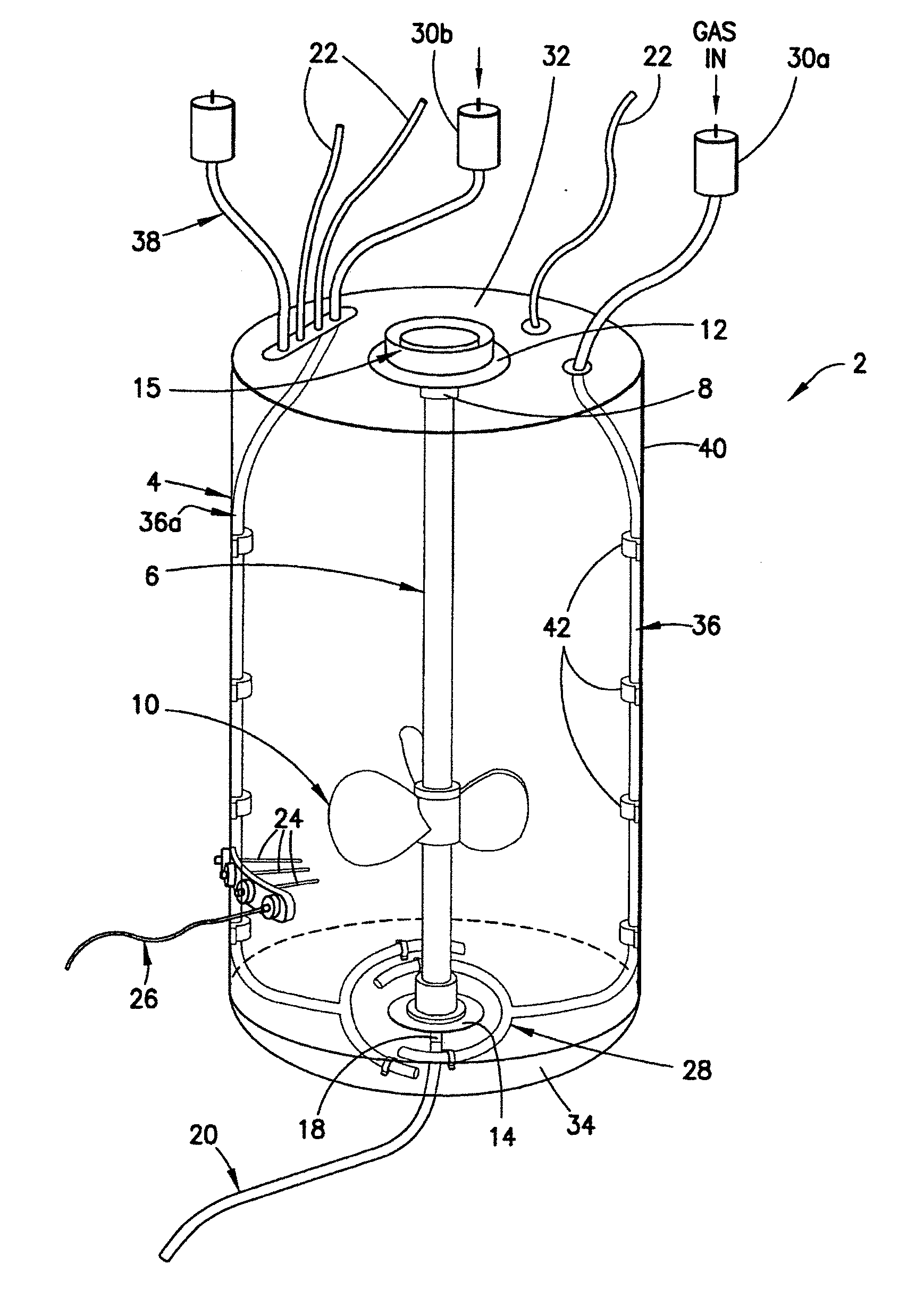
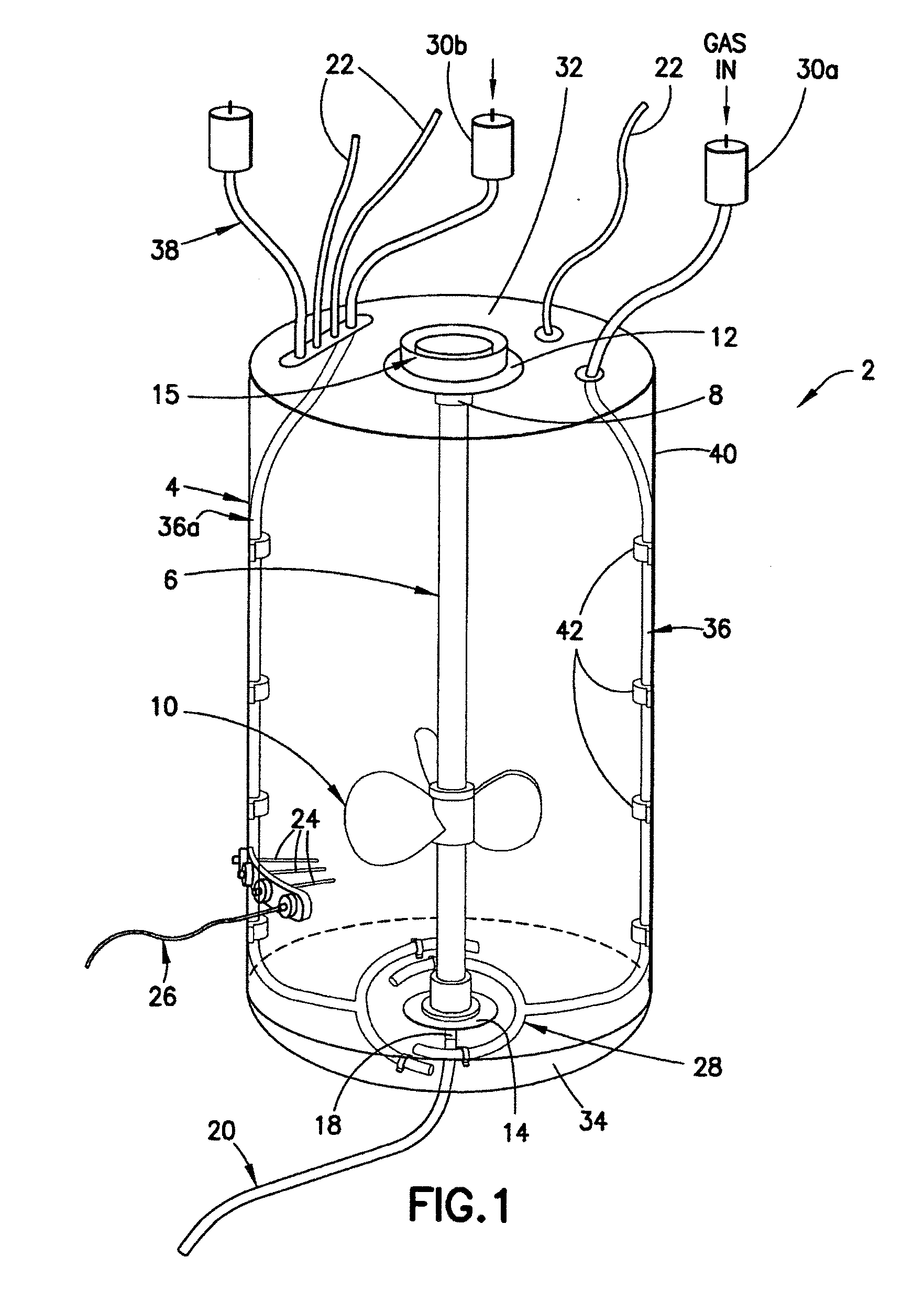
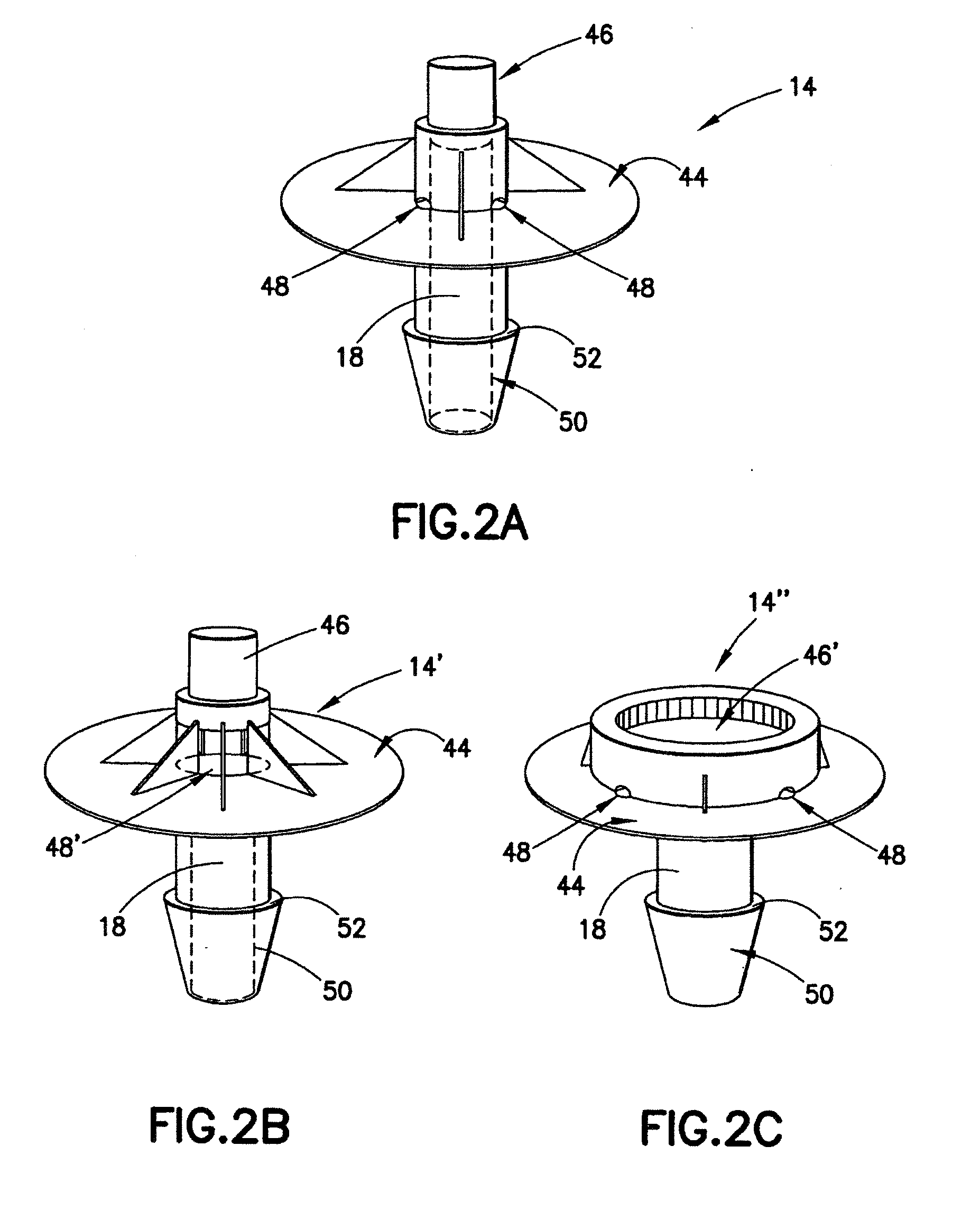
[0050]In one preferred embodiment, as shown in FIG. 1, the disposable mixing vessel 2 of the present invention comprises a flexible container 4 having a centrally disposed shaft 6 with a magnetic element 8 at one end and one or more impellers 10 mounted thereon. The shaft 6 is associated with top and bottom flanges 12 and 14 on the vessel 2, and includes thrust bearings 74 between the shaft 6 and one or both of the flanges 12 and 14 for facilitating rotation of the shaft 6. The top flange 12 preferably includes a drive coupling 15 for receiving the magnetic drive element of a drive motor (not shown). The bottom flange 14 includes a drain port 18 with access to the interior of the vessel 2 for draining the vessel 2, preferably using a harvest line 20 attached to the drain port 18, after the mixing process has been completed.

[0051]The mixing vessel 2 includes one or more inlets 22 for filling the vessel 2 with the materials to be mixed. It is preferred that the vessel 2 incorporates o...


PUM

PropertyMeasurementUnit
volumesaaaaaaaaaa
flexibleaaaaaaaaaa
magneticaaaaaaaaaa

Abstract

A method of mixing including providing a flexible container which comprises at least two components, assembling the components from outside the flexible container to form a centrally disposed magnetic driven shaft with at least one impeller, whereby the integrity of the flexible container is maintained, filling the flexible container having the centrally disposed magnetic driven shaft with one or more ingredients of the contents to be mixed; engaging a magnetic element of the centrally disposed magnetic driven shaft with an external magnetic drive element; analyzing the contents of the flexible container using at least one sensor or a sampling line on the flexible container; and draining the contents of the flexible container through a drain port at the bottom of the flexible container.

Description

REFERENCE TO RELATED APPLICATION[0001]The present application claims priority to U.S. Provisional Patent Application No. 61 / 069,977, filed on Mar. 19, 2008.FIELD OF THE INVENTION[0002]The present invention relates to the field of mixing, preferably in a disposable mixing vessel and, more particularly, to a method of mixing in a disposable mixing vessel having self-contained, magnetically coupled mixing apparatus included within the mixing vessel as a unit.BACKGROUND OF THE INVENTION[0003]Agitator or mixing tanks with rotating agitator apparatus are typically used to mix chemical compounds. Frequently, the ingredients being mixed in the agitator tanks require a sterile environment, such as when ingredients are being mixed to prepare a pharmaceutical product. Although some applications do not require a sterile environment, the United States Food and Drug Administration has set out strict sterile requirements for some solutions. To provide such a sterile environment, mixing tanks must ...

Claims


Application Information

Patent Timeline
Patent Type & Authority Applications(United States)
IPC IPC(8): B01F13/08B01F15/02B01F3/04B01F27/91B01F33/40
CPCB01F3/04269C12M29/06B01F7/00691B01F7/1695B01F7/22B01F13/0827B01F15/00071B01F15/00123B01F15/00396B01F15/00707B01F15/00831B01F15/0085B01F15/065B01F2003/04326B01F2003/04361B01F2003/04879B01F2003/04893B01F2015/062B01F2215/0073C12M23/26C12M27/02B01F7/00633B01F23/23124B01F23/231266B01F23/231231B01F23/237612B01F23/23762B01F27/2121B01F27/191B01F27/88B01F27/91B01F33/453B01F33/4535B01F35/146B01F35/20B01F35/2215B01F35/4121B01F35/51B01F35/513B01F2035/99B01F35/92B01F2101/44
Inventor LUDWIG, JENSREIF, OSCAR-WERNERGRELLER, GERHARDKAHLERT, WOLFGANGPRADEL, GUENTHERBATES, MICHAELBARBAROUX, MAGAILBAUD, STEPHANEGAY, ISABELLECHAUSSIN, SEBASTIAN
Owner SARTORIUS STEDIM BIOTECH GMBH
Why Eureka
Try Eureka