Method and instrument for surgical navigation
a surgical navigation and current position technology, applied in the field of surgical navigation, can solve the problems of magnetic system failure to operate, camera being covered by the operating staff, upset or distort the magnetic field,
- Summary
- Abstract
- Description
- Claims
- Application Information
AI Technical Summary
Benefits of technology
Problems solved by technology
Method used
Image
Examples
first embodiment
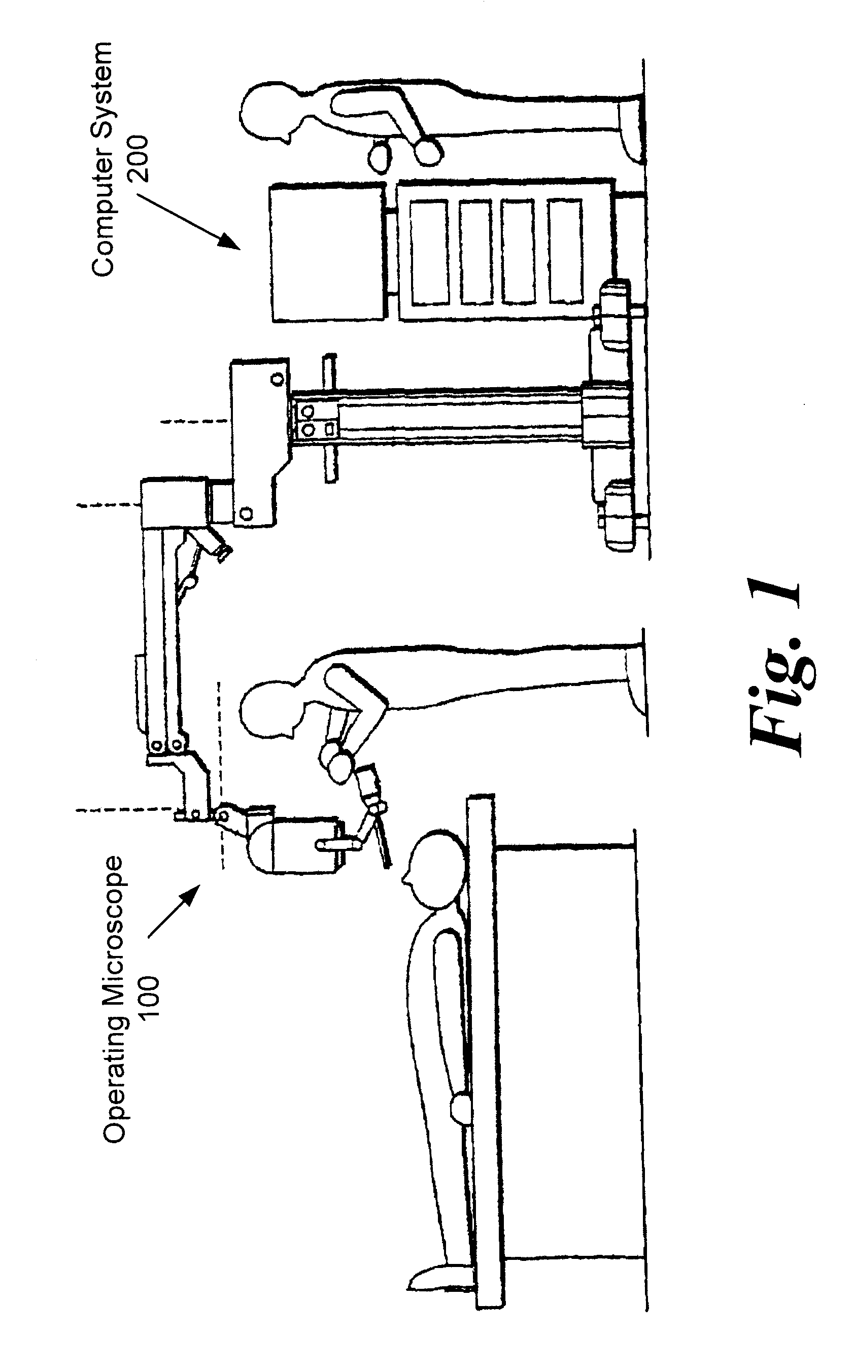
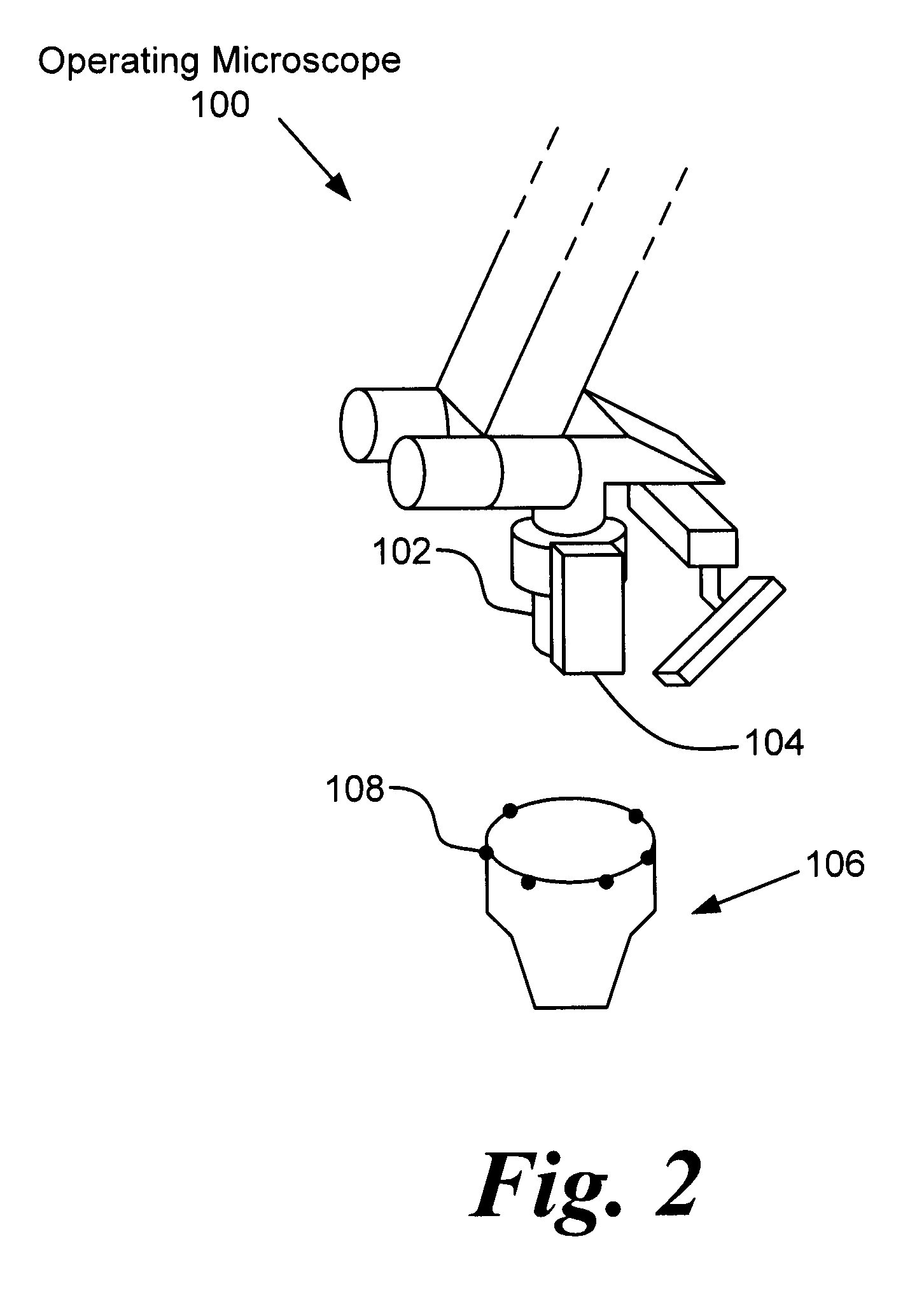
[0059]According to a first embodiment the field of operation lies inside the head of a patient, and an operating instrument is positioned with a corresponding marking in the field of view of the operating microscope.
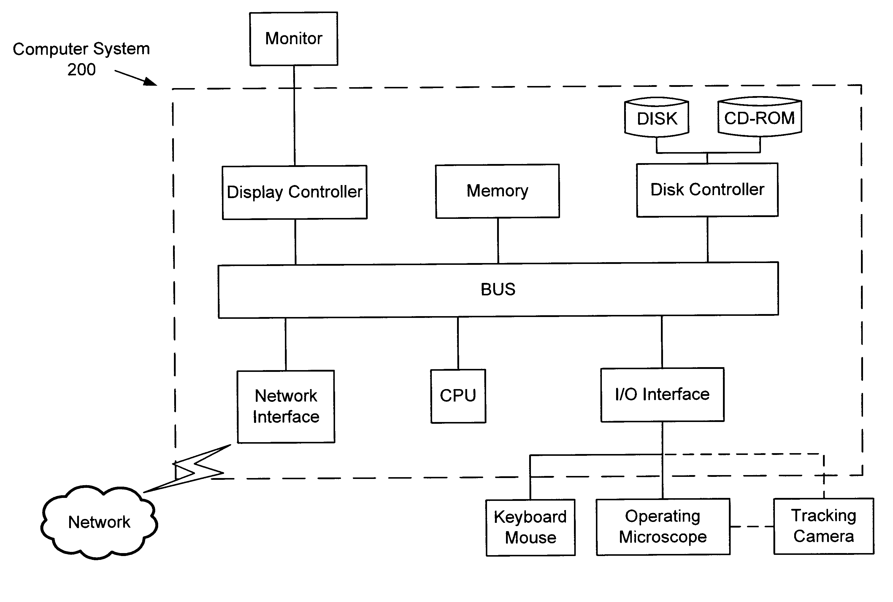
[0060]The images of both observation channels are led via a beam splitter to two image receivers, e.g. CCD cameras. The camera images are then evaluated by a computer, and the position of the operating instrument is calculated in the coordinate system of the microscope from the stereoscopic image analysis and the device parameters, such as zoom and focus settings, which are additionally outputted by the microscope via a data connection.
[0061]At the same time, the location of the microscope and the patient is detected in the coordinate system of the stereo camera arm by a stereo camera pair with corresponding cameras, which is positioned in the proximity of the operating table, by means of stereoscopic image analysis and with the aid of the patient markings and the micros...
second embodiment
[0077]The procedure according to the second embodiment is largely analogous to the first embodiment. Instead of the two cameras coupled to the observation channel of the microscope, however, one of the cameras is replaced by a diaphragm. The same lens system, which had previously imaged the object field onto said camera, is now used to image the diaphragm onto the object field. If a diaphragm structured with points, lines or gratings is used, and light is led through said diaphragm structures and the associated optical channel onto the object field, and if the correspondingly illuminated area is recorded with the remaining camera, the principle of the inverse camera is applicable, and the methods of stereoscopic image analysis are usable despite the use of one camera only. With respect to the error security here, too, the advantages of the first embodiments apply. If invisible light is used, visible light may additionally be admixed so as to make the supporting points of the topogra...
third embodiment
[0078]In a third embodiment a PMD sensor array is used instead of the conventional cameras. For being able to use the same, modulated light must be used for illumination in addition to the visible light of the microscope. The PMD sensor is protected against a too intensive illumination by the white non-modulated light by suited optical filters. The topography of the field imaged on the PMD sensor array may be obtained with this new technology directly from the PMD chip with an associated computer having a suited interface.
[0079]The topographical data obtained in the above embodiments can then, for example, as three-dimensional perspective grating or in the form of contour lines or the like, be represented on a display. Moreover, said topographical data can be represented location-correlated with data from preoperative diagnostic data (nuclear resonance scanning data, computerized tomography data etc.).
PUM
 Abstract
Description
Claims
Application Information
 - R&D
- Intellectual Property
- Life Sciences
- Materials
- Tech Scout
- Unparalleled Data Quality
- Higher Quality Content
- 60% Fewer Hallucinations
Browse by: Latest US Patents, China's latest patents, Technical Efficacy Thesaurus, Application Domain, Technology Topic, Popular Technical Reports.
© 2025 PatSnap. All rights reserved.Legal|Privacy policy|Modern Slavery Act Transparency Statement|Sitemap|About US| Contact US: help@patsnap.com


