
Flexible thermal ground plane and manufacturing the same

a flexible, ground plane technology, applied in the direction of basic electric elements, semiconductor devices, lighting and heating apparatus, etc., can solve the problems of limited complexity and size of integrated circuits, and achieve the effects of effective liquid supply, high thermal performance, and high evaporation/condensation heat transfer

Active Publication Date: 2011-01-27
KELVIN THERMAL TECH
View PDF19 Cites 130 Cited by
  • Summary
  • Abstract
  • Description
  • Claims
  • Application Information

AI Technical Summary

Benefits of technology

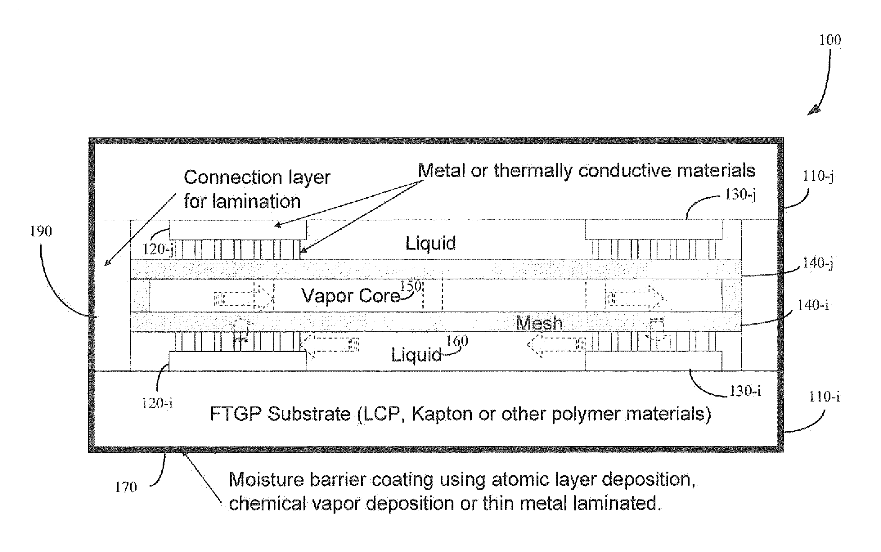
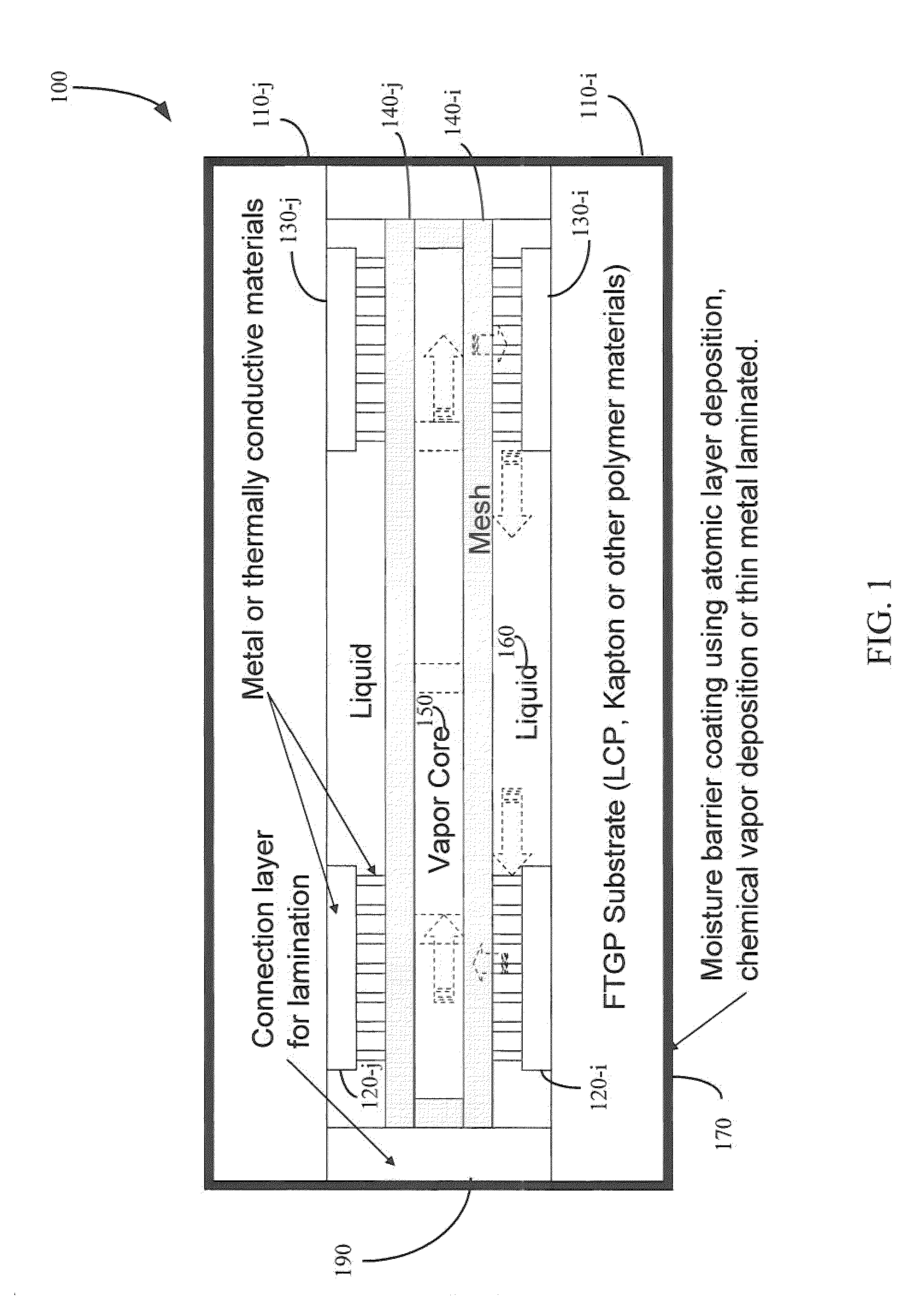
[0006]Certain embodiments thus provide methods, systems, and devices that may include a flexible thermal ground plane. Embodiments of flexible thermal ground planes may provide extremely high thermal performance with high evaporation / condensation heat transfer and effective liquid supply. Flexible configurations may be enabled by using polymer casing laminated and covered by moisture barrier coatings, enabled by atomic layer deposition, chemical vapor deposition, physical vapor deposition, or thin metal laminate, merely by way of example. Embodiments of flexible thermal ground planes may also involve low cost construction resulting from large size manufacturing, e.g. 3 ft wide and 1000 ft long, merely by way of example. For example, flexible thermal ground plane construction may take advantage of flexible circuit board manufacturing technology. Large size flexible thermal ground planes may thus be constructed for some embodiments, e.g. 20 cm by 40 cm by 1 mm, merely by way of example.

Problems solved by technology

The complexity and size of integrated circuits may been limited by the heat generated.

Method used


Image

  • Flexible thermal ground plane and manufacturing the same
  • Flexible thermal ground plane and manufacturing the same
  • Flexible thermal ground plane and manufacturing the same

Examples


Embodiment Construction

[0063]The ensuing description provides exemplary embodiments only, and is not intended to limit the scope, applicability or configuration of the disclosure. Rather, the ensuing description of the exemplary embodiments will provide those skilled in the art with an enabling description for implementing one or more exemplary embodiments. It being understood that various changes may be made in the function and arrangement of elements without departing from the spirit and scope of the invention as set forth in the appended claims.

[0064]Specific details are given in the following description to provide a thorough understanding of the embodiments. However, it will be understood by one of ordinary skill in the art that the embodiments may be practiced without these specific details. For example, circuits, systems, networks, processes, and other elements in the invention may be shown as components in block diagram form in order not to obscure the embodiments in unnecessary detail. In other i...


PUM

PropertyMeasurementUnit
sizeaaaaaaaaaa
sizeaaaaaaaaaa
widthaaaaaaaaaa

Abstract

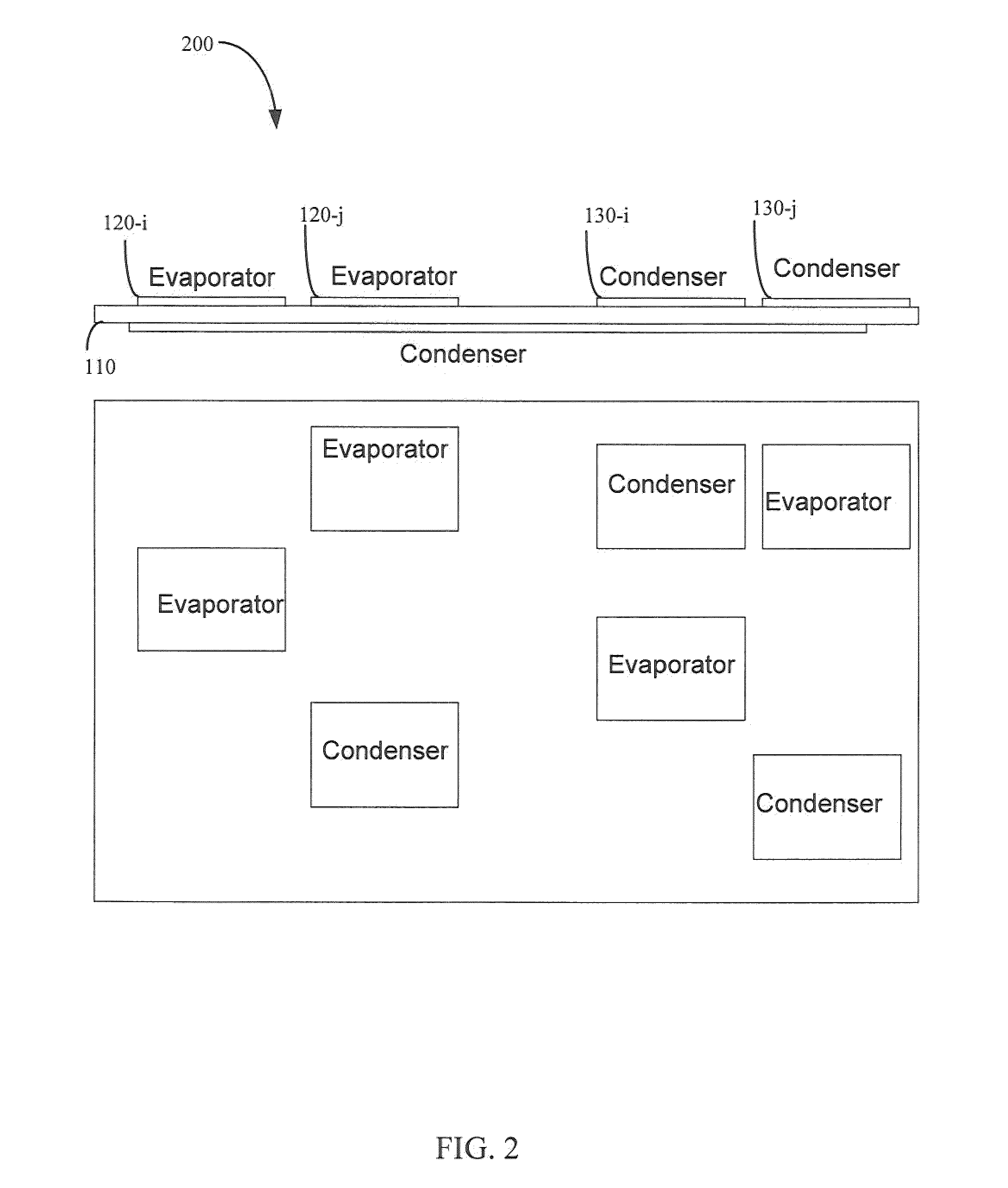
Methods, apparatuses, and systems are disclosed for flexible thermal ground planes. A flexible thermal ground plane may include a support member. The flexible thermal ground plane may include an evaporator region or multiple evaporator regions configured to couple with the support member. The flexible thermal ground plane may include a condenser region or multiple condenser regions configured to couple with the support member. The evaporator and condenser region may include a microwicking structure. The evaporator and condenser region may include a nanowicking structure coupled with the micro-wicking structure, where the nanowicking structure includes nanorods. The evaporator and condenser region may include a nanomesh coupled with the nanorods and / or the microwicking structure. Some embodiments may include a micromesh coupled with the nanorods and / or the microwicking structure.

Description

CROSS-REFERENCES TO RELATED APPLICATIONS[0001]This application is a non-provisional claiming priority benefit of U.S. provisional patent application Ser. No. 61 / 158,086, filed on Mar. 6, 2009 and entitled “Flexible Thermal Ground Plane and Manufacturing the Same and Means to Fabricate a Flexible Thermal Ground Plane,” the entire disclosure of which is herein incorporated by reference for all purposes.STATEMENT AS TO RIGHTS TO INVENTIONS MADE UNDER FEDERALLY SPONSORED RESEARCH AND DEVELOPMENT[0002]This invention was made with government support under Grant No. N66001-08-C-2006 awarded by DOD / DARPA and Grant No. HR0011-06-1-0048 awarded by the DOD / DARPA. The government has certain rights in the invention.BACKGROUND[0003]This application relates generally to thermal ground planes. More specifically, this application relates to methods, apparatuses, and systems for flexible thermal ground planes.[0004]The complexity and size of integrated circuits may been limited by the heat generated....

Claims


Application Information

Patent Timeline
Patent Type & Authority Applications(United States)
IPC IPC(8): F28D15/04B21D53/02
CPCF28D15/046H01L23/3677H01L23/427F28D15/0233Y10T29/49353H01L2924/0002F28D15/0241H01L2924/00B23P15/26F28D15/04H01L23/473B23P2700/09
Inventor YANG, RONGGUILEE, Y.C.BRIGHT, VICTOR M.LI, CHENPETERSON, G.P. BUDOSHMAN, CHRISTOPHERSHI, BOCHENG, JEN-HAU
Owner KELVIN THERMAL TECH
Learn More