Self powered mili, micro, and nano electronic chips

Inactive Publication Date: 2011-01-27
JAY ERIC +2
View PDF13 Cites 1 Cited by
  • Summary
  • Abstract
  • Description
  • Claims
  • Application Information

AI Technical Summary

Benefits of technology

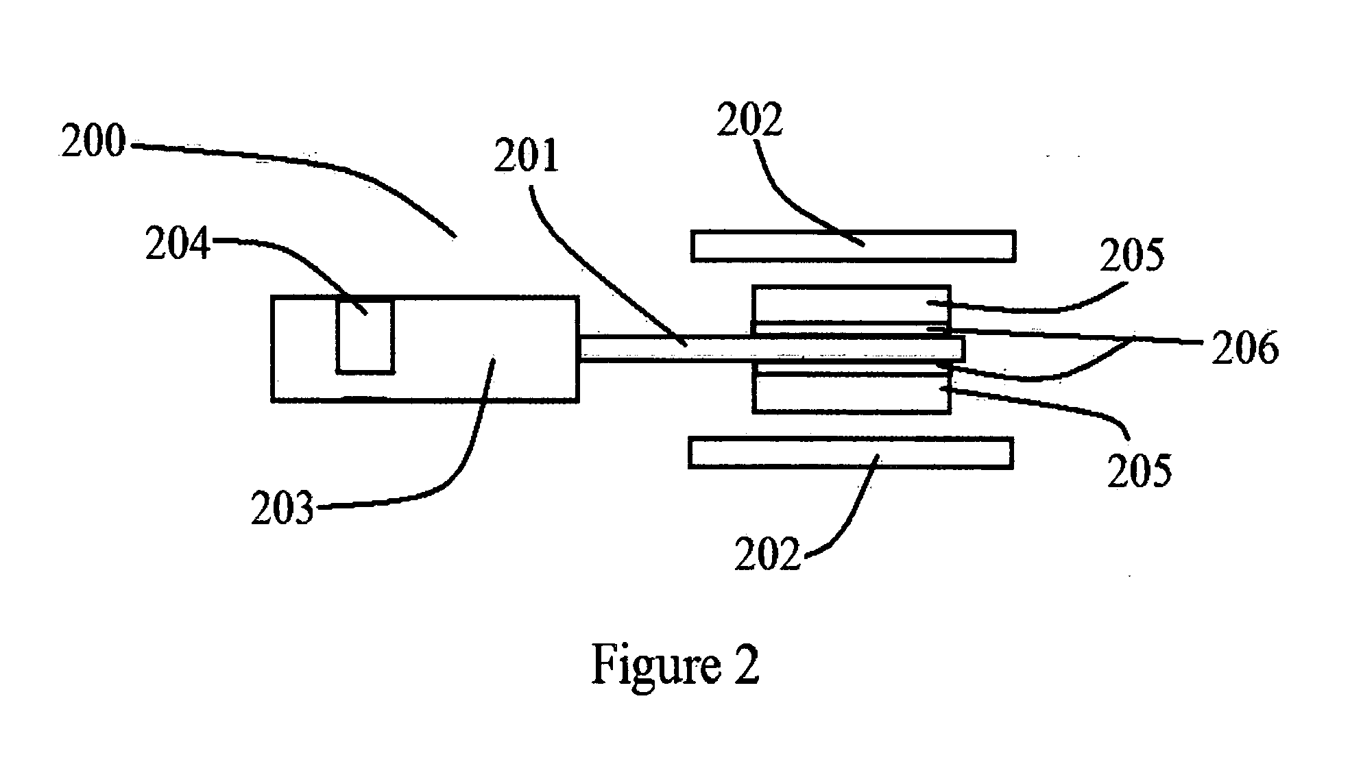
[0023]FIG. 4 is a diagrammatical front view of multiple carbon nanotubes, which have been layered with magnetic bacteria located between two coil structures and of varying lengths. The varying lengths facilitate using multiple frequenc

Problems solved by technology

There is no prior art developments using magnetic bacteria for this type of power generation.

Method used


Image

  • Self powered mili, micro, and nano electronic chips
  • Self powered mili, micro, and nano electronic chips
  • Self powered mili, micro, and nano electronic chips

Examples


Embodiment Construction

[0026]In the following description, certain details are set forth in order to provide a thorough understanding of the various embodiments of devices, methods, and articles. However, one skilled in the art will understand that other embodiments may be practiced without these details. In other instances, well known structures and methods associated with coils and magnetic assemblies have not been shown or described in detail to avoid unnecessary obscuring descriptions of the embodiments.

[0027]Unless the content requires otherwise, throughout the specifications and claims which follow, the word “comprise” and variations thereof such as “comprising” and “comprises” are to be constructed in an open, inclusive sense, that is as “including, but not limited to.”

[0028]References throughout this specification to “one embodiment,” or “an embodiment” means that a particular feature, structure or characteristic described in connection with the embodiment is included in at least one embodiment. T...


PUM


Abstract

Self powered mico, mili, and nano electronic chips having one or more methods of self-power production. Comprising a series of carbon nanotubes with attached magnetic bacteria for creating vibration with the existing Radio Frequency (RF) fields of the oscillators included in the electronic device or ambient RF fields across coils. As well as a layer of Ni—Mn—Ga magnetoplastic layer which is deformed by magnetic flux lines to cause current flow thorough coils of wire. This configuration creates a power generator on the chipset comprising of magnetic fields and a coil configured to focus the magnetic field in the electrical conductive elements of the coil.

Description

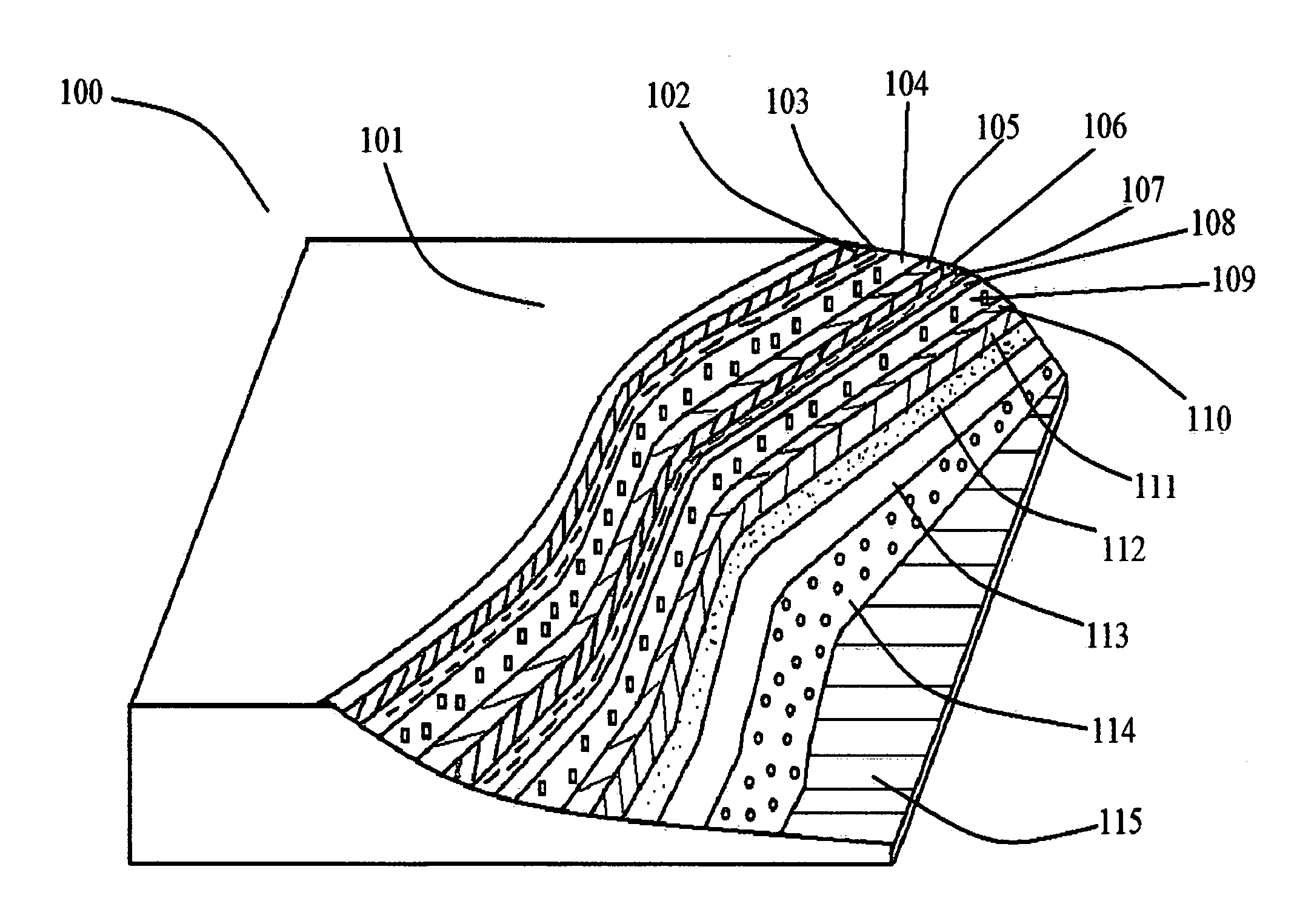
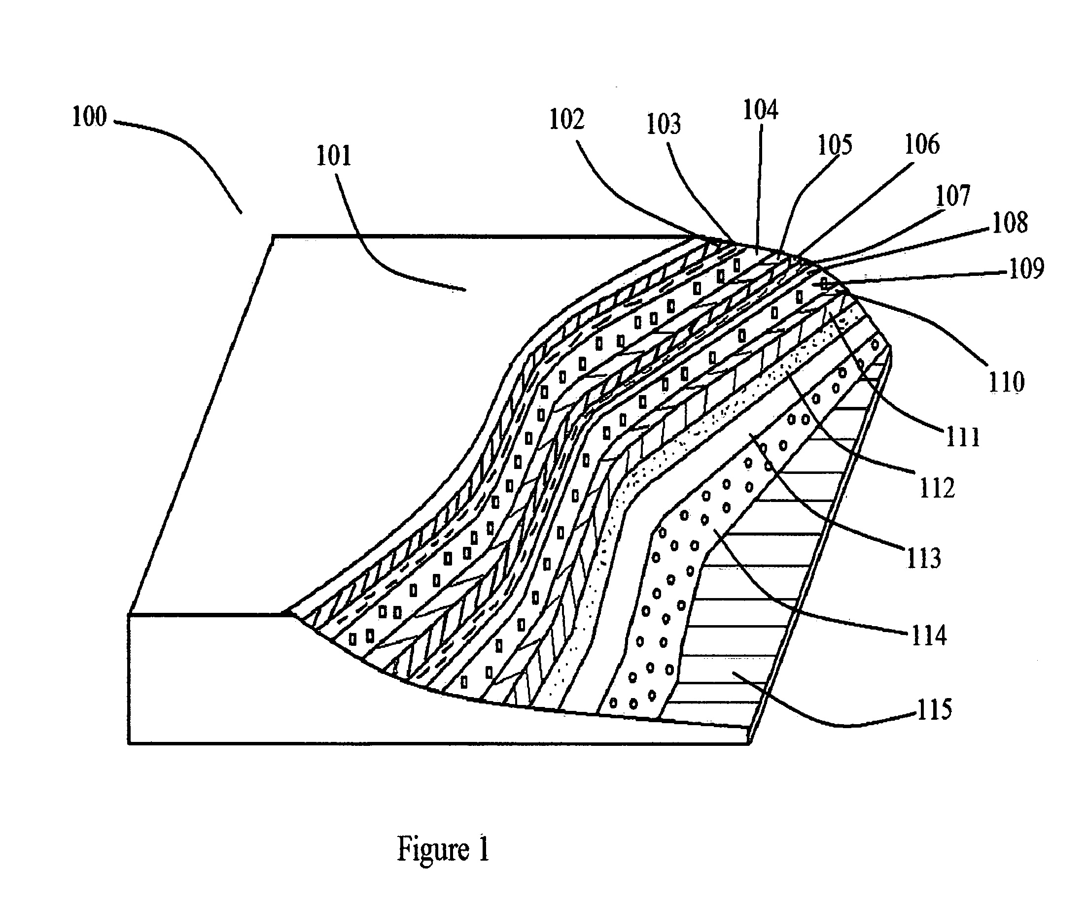
U.S. PATENT DOCUMENTS[0001]4,385,119 AMay 1983Blakemore435 / 16834,394,451 AJuly 1983Blakemore435 / 253.64,452,896 AJune 1984Blakemore435 / 252.15,590,031 ADecember 1996Mead363 / 85,703,474 ADecember 1997Smalser323 / 2996,766,141 AJuly 2004Briles455 / 406,818,470 ANovember 2004Acklin438 / 557,084,605 AAugust 2006Mickle320 / 1017,514,804 AApril 2009Wang290 / 1R7,567,824 AJuly 2009Mickle455 / 5737,749,727 AJuly 2010Sheppard435 / 29FOREIGN PATENT DOCUMENTS[0002]7,161,245 AJanuary 2007Saito257 / 737OTHER PUBLICATIONS[0003]None citedSTATEMENT REGARDING GOVERNMENT INTEREST[0004]This invention was not made under any United States Government Contract. Therefore the United States Government has no rights in the invention.BACKGROUND OF THE INVENTION[0005]1. Field of the Invention[0006]This disclosure generally relates to a system and methods for developing electronic micro, mili, and nano chips that will harvest electrical signals, converting energy into an electrical current and storing the energy from electronics ...

Claims


Application Information

Patent Timeline
IPC IPC(8): H02J17/00
CPCH02J17/00H02J5/005B82Y30/00H02J50/10H02J50/001H02J50/20
Inventor JAY, ERICYARGER, REX DALEYARGER, ERIC JOHN
Owner JAY ERIC
Why Eureka
Try Eureka