

Organic electroluminescence element
a technology of electroluminescent elements and organic elements, which is applied in the direction of discharge tube/lamp details, discharge tube main electrodes, incadescent cooling arrangements, etc., can solve the problems of deterioration of organic el elements themselves, affecting the manner in which heat is released from devices, and reducing light-emitting properties, etc., to achieve excellent heat dissipation and simple structure
- Summary
- Abstract
- Description
- Claims
- Application Information
AI Technical Summary
Benefits of technology
Problems solved by technology
Method used
Image

Examples
first embodiment
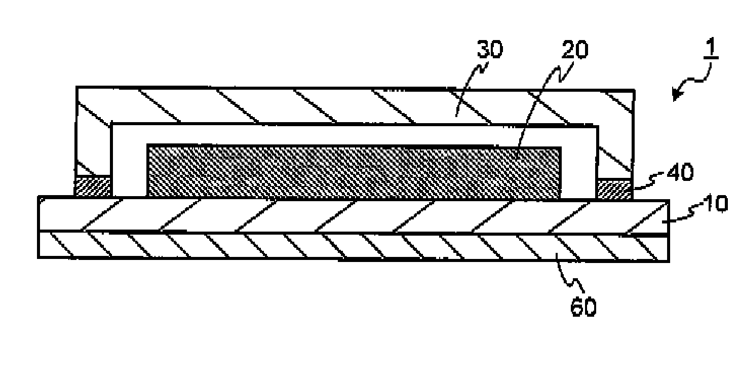
[0067]The first embodiment of the present invention is described with reference to FIG. 1. FIG. 1 is a sectional schematic of an organic EL element 1 of the first embodiment (hereinafter, referred to as an “element of the first embodiment”). In the element of the first embodiment, a layered body 20 including an organic light-emitting layer is formed on a supporting substrate 10. The whole of the layered body 20 is covered with a sealing substrate 30, and the sealing substrate 30 and the supporting substrate 10 are sealed at a adhesive portion 40. With such a structure, the layered body 20 is isolated from the external environment. A highly thermally radiative layer 60 is provided on the face outside of the supporting substrate 10, that is, at the face opposite to the side on which the layered body 20 is formed.
[0068]In the organic EL element 1, heat generated in the element is diffused in the substrate to promote uniform heating, and a heat radiation mechanism is provided to more ac...
second embodiment
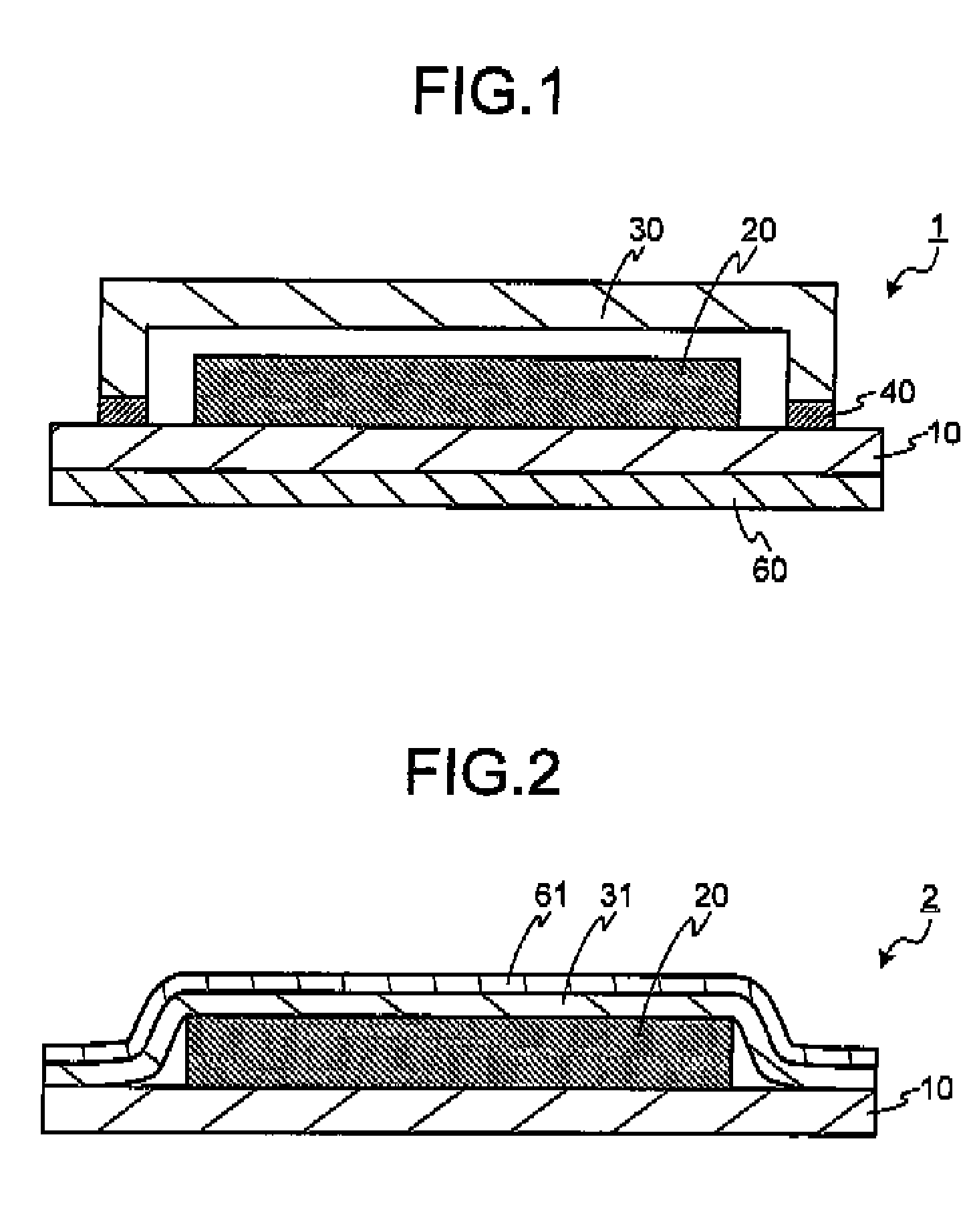
[0157]A second embodiment of the present invention is described with reference to FIG. 2. FIG. 2 is a sectional schematic of an organic EL element 2 of the second embodiment (hereinafter, referred to as an “element of the second embodiment”). In FIG. 2, the same numerals as those in FIG. 1 are given to the same or similar components as or to those in the first embodiment, and the points different from the first embodiment are mainly described below.
[0158]In the organic EL element 2, a highly thermally radiative layer 61 is provided on the face outside of a sealing substrate 31, that is, at the face on the side opposite to the layered body 20. A glass substrate or a sheet material having plasticity is used for the sealing substrate 31, and the sealing substrate 31 adheres to the supporting substrate 10. In other words, as illustrated in the organic EL element 2, the highly thermally conductive and radiative layer 61 may be provided on the side of the sealing substrate 30.
third embodiment
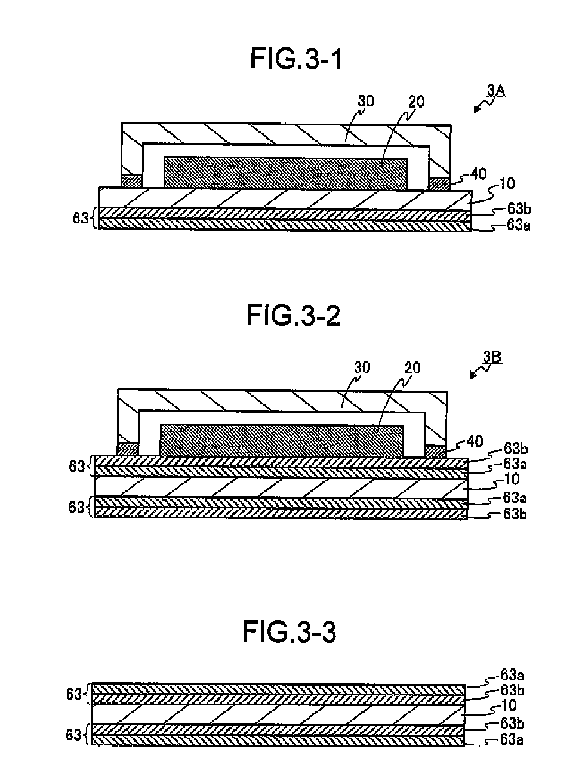
[0159]A third embodiment of the present invention and modified examples are described with reference to FIG. 3-1 to FIG. 3-5. FIG. 3-1 is a sectional schematic of an organic EL element 3A of the third embodiment (hereinafter, referred to as an “element of the third embodiment”). In FIG. 3-1, the same numerals as those in FIG. 1 are given to the same or similar components as or to those in the first embodiment, and the points different from the first embodiment are mainly described below.
[0160]In the organic EL element 3A, a highly thermally conductive and radiative layer 63 is provided on the face outside of the supporting substrate. The highly thermally conductive and radiative layer 63 is composed of two layers. One of the layers is a black coating layer 63a, and the other is an aluminum layer 63b. Heat is conducted to the supporting substrate 10 due to the heat generation of the organic light-emitting layer. Heat is prone to remain in the supporting substrate 10 particularly when...
PUM
 Abstract
Description
Claims
Application Information