
Shunt driver circuit for semiconductor laser diode

Active Publication Date: 2011-01-27
SUMITOMO ELECTRIC IND LTD
View PDF6 Cites 5 Cited by
  • Summary
  • Abstract
  • Description
  • Claims
  • Application Information

AI Technical Summary

Benefits of technology

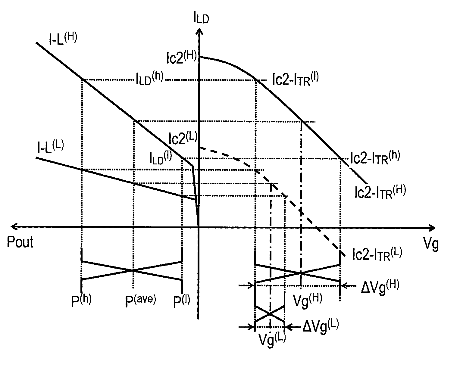
[0007]When the temperature of the LD is relatively low, the bias generator provides the bias with relatively smaller to the switching transistor, while, the temperature of the LD is high, the bias generator increases the bias to modulate the LD enough. Thus, because the bias for the switching transistor follows the change in the temperature of the LD, the total power consumption of the driver circuit may be reduced.
[0009]Moreover, the driver circuit of the present invention may further provide the APC circuit to keep constant in the average power and the extinction ratio of the light output from the LD. The APC circuit may output a control signal to the bias current source to vary the bias current as the temperature of the LD changes. The bias current source, receiving the control signal from the ABC circuit, may vary the bias supplied to the switching transistor. Thus, the bias may be indirectly depends on the temperature of the LD.
[0010]The driver circuit of the present invention may further provide a pre-amplifier to output a driving signal to the switching transistor. The APC circuit may output another control signal to the pre-amplifier to vary the amplitude of the driving signal therefrom. The switching transistor receives the driving signal provided from the pre-amplifier superposed with the bias provided from the bias generator. Because both the driving signal and the bias indirectly follow the temperature of the LD through the APC circuit, the total power consumption of the driver circuit may be reduced.

Problems solved by technology

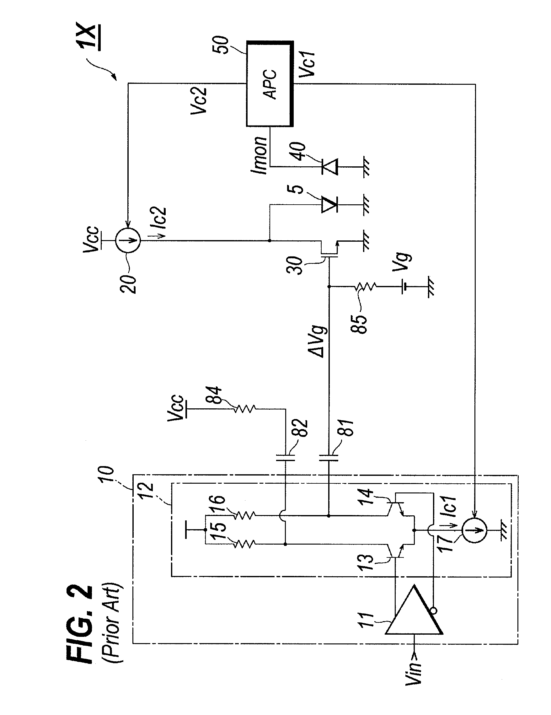
However, a conventional shunt-driver circuit somewhat bounds the bias condition at a high temperature even in a low temperature; accordingly, unnecessary idle current is supplied to the LD or the switching transistor connected in parallel to the LD is left in a lower temperature, which becomes hard to reduce the power consumption.

Method used


Image

  • Shunt driver circuit for semiconductor laser diode
  • Shunt driver circuit for semiconductor laser diode
  • Shunt driver circuit for semiconductor laser diode

Examples


Embodiment Construction

[0021]Next, preferred embodiments according to the present invention will be described as referring to accompanying drawings. In the description of the drawings, the same elements will be referred by the same elements or symbols without overlapping explanations.

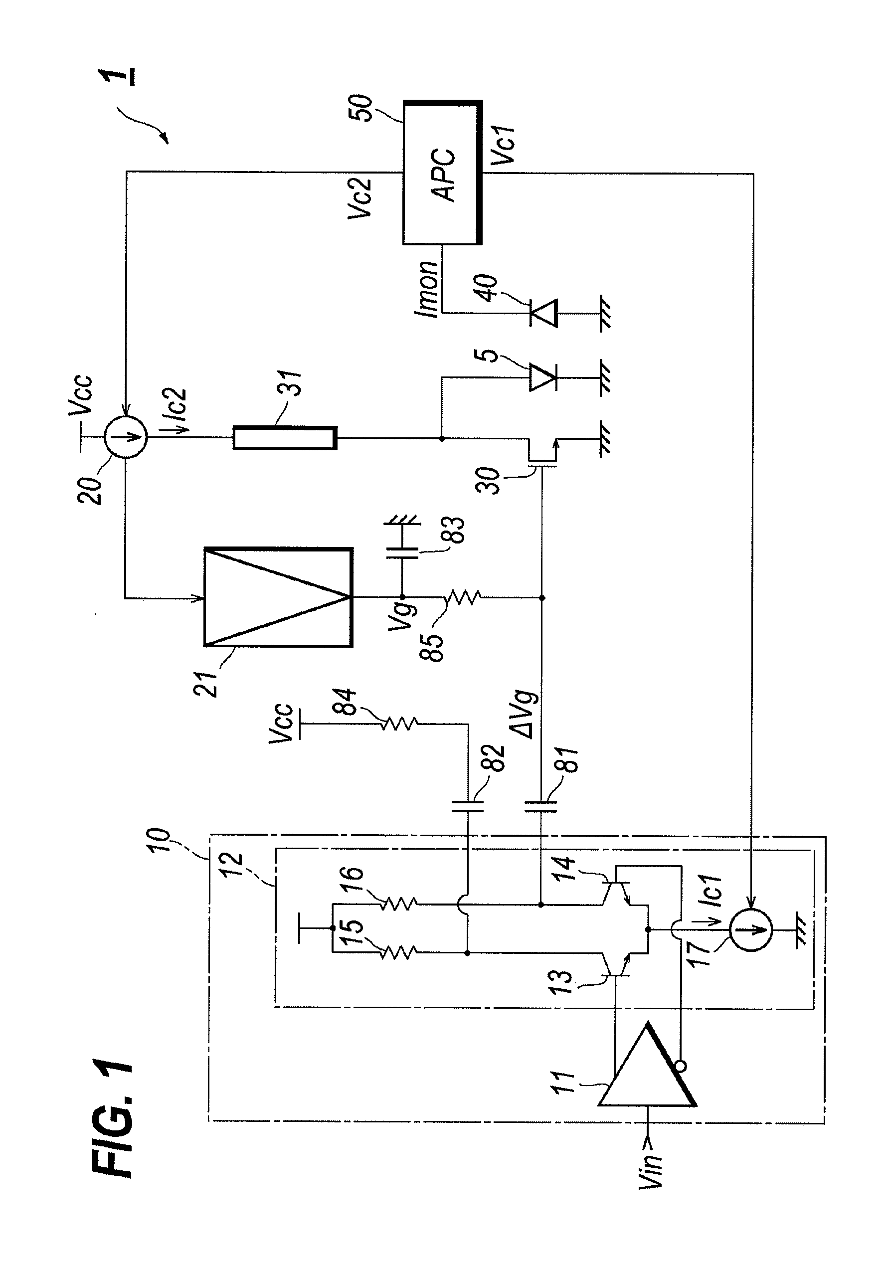
[0022]FIG. 1 is a circuit diagram of a laser driver (hereafter denoted as LD-driver) according to an embodiment of the present invention. The LD driver 1, which electrically drives the semiconductor laser diode (hereafter denotes as LD) 5, comprises a pre-amplifier section 10, the bias current source 20, the switching transistor 30, the semiconductor photodiode (hereafter denoted as PD) 40, the auto-power control (APC) circuit 50, the current mirror circuit 60, the bias generator 70, capacitors, 81 to 83, and termination resistors, 84 and 85.

[0023]The pre-amplifier section 10, which generates the modulation signal Vm by receiving the input driving signal Vin, includes the pre-amplifier 11 and the differential circuit 12 conne...


PUM


Abstract

A driver circuit for the laser diode is disclosed. The driver circuit has the shunt configuration with a switching transistor connected in parallel to the laser diode to shunt the current flowing in the laser diode. In the present invention, the bias for the switching transistor is varied as the operating temperature of the laser diode. In addition, the gate bias for the switching transistor is compensated for the temperature dependence of the switching transistor.

Description

BACKGROUND OF THE INVENTION[0001]1. Field of the Invention[0002]The present invention relates to a driver circuit for a semiconductor laser diode (hereafter denoted as LD), in particular, the inventions relates to a driver circuit with a shunt-driving configuration.[0003]2. Related Background Art[0004]The shunt driver for the LD has been well known as one type of the driver circuit. For instance, U.S. Pat. No. 5,513,197, has disclosed the laser driver circuit with the shunt-driving configuration. The shunt-driving configuration provides a switching transistor connected in parallel to the LD and shunts the bias current flowing in the LD by this switching transistor to modulate the LD. In a practical application for the LD such as an optical transmitter installed in the optical communication, two conditions are inevitable, that is, the average output power and the extinction ratio of the light emitted from the LD must be constant independent of both internal and external conditions. T...

Claims


Application Information

Patent Timeline
IPC IPC(8): H01S3/00
CPCH01S5/0427H01S5/06832H01S5/06808H01S5/06804
Inventor MOTO, AKIHIROTANAKA, KEIJI
Owner SUMITOMO ELECTRIC IND LTD
Learn More