Microfluidic device and method

a micro-fluidic and fluid technology, applied in the direction of positive displacement liquid engines, laboratory glassware, machines/engines, etc., can solve the problems of difficult or even impossible electrothermal fluid flow, low efficiency of electrothermal fluid flow, and inability to use simple electrodes. , to achieve the effect of shortening the length of the respective electrod

Inactive Publication Date: 2011-01-27
KONINKLIJKE PHILIPS ELECTRONICS NV
View PDF10 Cites 12 Cited by
  • Summary
  • Abstract
  • Description
  • Claims
  • Application Information

AI Technical Summary

Benefits of technology

[0009]It is an object of the present invention to provide an improved micro fluidic device and method, in particular having a simpler and smaller design.

Problems solved by technology

This is a disadvantage because the pumping effect strongly depends on the properties of both the particles and the liquid.
Both blood and saliva are high conductivity liquids and as such make electro-osmosis and even electrothermal fluid flow extremely difficult or even impossible.
So there is currently not a good technique based on simple electrodes only which is able to pump high conductivity liquids.
DC electric fields, however, do not easily penetrate liquids with high concentrations of charged species and a current can only be drawn when hydrolysis (charge neutralization) occurs at the electrodes.
Hydrolysis creates gas bubbles in the fluid and is not a desired effect in microfluidics because bubbles disturb or even can block the liquid flow.
These electromagnets are bulky, consume a lot of power, are not integrated directly onto a substrate and cannot easily be oscillated above 10 kHz due to their high inductance.

Method used


Image

  • Microfluidic device and method
  • Microfluidic device and method
  • Microfluidic device and method

Examples


third embodiment

[0057]A cross-section of an MHD cell 90 according to the present invention is shown in FIG. 7. In this embodiment only one substrate 98 is provided within the microfluidic channel 101 carrying all electrodes 91-94. In particular, the substrate 98 carries on its surface a pair of electric field electrodes 91, 92 provided with an electric potential +V, −V from a voltage source 95 and magnetic field electrodes 93, 94 provided with electric currents +I, −I from separate current sources 96, 97.

[0058]Similarly as in the embodiment shown in FIG. 6, a control unit 100 is provided for control of the voltage source 95 and the current sources 96, 97 to simultaneously provide the electric potential +V, −V and the electric currents +I, −I, respectively. Thus, a Lorentz force is generated in the direction 99 of the channel 101.

fourth embodiment

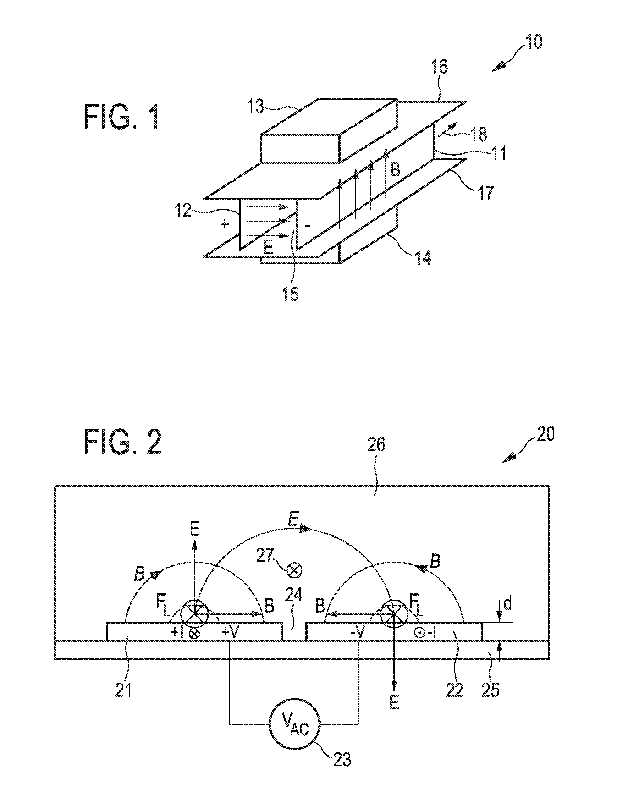
[0059]FIG. 8 shows a cross section of an MHD cell 20′ according to the present invention. This embodiment is quite similar to the embodiment shown in FIG. 2, but in the present embodiment a voltage source 23 for providing the electric potential +V, −V to the electrodes 21, 22 and a current source 28 for providing a current +I to only the electrode 21 are separately provided. Further, a control unit 29 for synchronizing the voltage source 23 and the current source 28 are provided.

[0060]Hence, according to this embodiment, a magnetic field B is only generated by the current +I through the electrode 21 which is generally sufficient for generating—in combination with the electric field E—a Lorentz force.

fifth embodiment

[0061]FIG. 9 shows a cross section of an MHD cell 90′ according to the present invention. This embodiment is quite similar to the embodiment shown in FIGS. 7 and 8. The present embodiment, however, comprises only a single magnetic field electrode 93 and a single current source 96, separate from the electric field electrodes 91, 92 and the voltage source 95. Thus, like in the embodiment shown in FIG. 8, only one current +I is provided for generating a magnetic field B.

[0062]This is one example of a more general case which is that of two coplanar substrates opposite to each other in such a way that magnetic and electric fields enhance each other. With respect to an embodiment with opposite sides, there are 2 configurations: a) two coplanar substrates where each individual coplanar substrate provides a Lorentz force, and (b) one side carries the voltage-driven electrodes while the other side carries the current-driven electrodes. In this case both sides are necessary to provide the Lor...


PUM


Abstract

The present invention relates to a microfluidic device and a corresponding method for pumping of high conductivity liquids comprising: —a microfluidic channel (26; 80; 101) for containing an electrically conductive liquid, in particular a liquid having a high conductivity, —at least two electric field electrodes (21, 22; 71, 72; 91, 92) for generating electric fields, —at least one magnetic field electrode (21, 22; 75, 76; 93, 94) for generating a magnetic field in a direction substantially perpendicular to said electric fields, —a voltage source (23; 74; 95) for providing electric potentials to said at least two electric field electrodes (21, 22; 71, 72; 91, 92) for generating said electric fields, —a current source (23; 78, 79; 96, 97) for providing an electric current to said at least two magnetic field electrodes (21, 22; 75, 76; 93, 94) for generating said magnetic field, wherein said voltage source (23; 74; 95) and said current source (23; 78, 79; 96, 97) are adapted to simultaneously provide said electric potential and electric current, respectively, to said electrodes to obtain a Lorentz force acting on the high conductivity liquid in the direction (27; 81; 99) of said microfluidic channel (26; 80; 101).

Description

FIELD OF THE INVENTION[0001]The present invention relates to a micro fluidic device and a corresponding method for pumping of high conductivity liquids.BACKGROUND OF THE INVENTION[0002]Handheld medical devices e.g. for Point-of-Care testing are becoming more and more of interest. In these devices high conductivity liquid samples such as blood or saliva have to be analyzed for specific biomarkers or biomolecules to indicate the health status of the person. The volume of the liquid samples is small and manipulation of the liquid is done in microfluidic channels and chambers. Manipulation typically includes transport of the liquid from the inlet port to the measurement site and mixing of several liquids. While in some cases the capillary force can be utilized many applications require active pumping for either transport or mixing.[0003]Active pumping mechanisms are typically divided into mechanical and non-mechanical pumps. Non-mechanical pumps have the advantage that they do not requi...

Claims


Application Information

Patent Timeline
Patent Type & Authority Applications(United States)
IPC IPC(8): H02K44/00
CPCB01L3/50273B01L2400/0415B01L2400/043H02K44/04B03C1/286F04B19/006B03C1/023
Inventor VAN ZON, HANSGILLIES, MURRAY FULTONCRAUS, CRISTIAN BOGDANCATTANEO, STEFANO
Owner KONINKLIJKE PHILIPS ELECTRONICS NV
Why Eureka
Try Eureka