
Method for testing piezoelectric/electrostrictive device, testing apparatus, and method for adjusting piezoelectric/electrostrictive device

Inactive Publication Date: 2011-02-03
NGK INSULATORS LTD
View PDF12 Cites 9 Cited by
  • Summary
  • Abstract
  • Description
  • Claims
  • Application Information

AI Technical Summary

Benefits of technology

[0011]The present invention has been made in view of such problems and aims to provide a means capable of testing a piezoelectric / electrostrictive device (piezoelectric / electrostrictive actuator and piezoelectric / electrostrictive sensor) highly precisely without actually driving the device as a product and without being accompanied by any disassembly / breakage.
[0063]In a method for adjusting a piezoelectric / electrostrictive sensor of the present invention, it is preferable that the trimming is performed in a portion having the maximum amplitude in the first order of the resonance mode. This makes the probability of inducing another vibration mode, and a vibration mode similar to that of a piezoelectric / electrostrictive actuator without trimming can be realized. As a result, it becomes possible to adjust the detection sensitivity with suppressing the change in the first or higher orders of the resonance frequency to the minimum.

Problems solved by technology

However, the former method requires high costs when the test is performed for all the lots of the piezoelectric / electrostrictive actuators manufactured.
In addition, the latter method does not always have high testing precision because the constituents other than the piezoelectric / electrostrictive actuating portion of the piezoelectric / electrostrictive actuator are not reflected to the test.
In such a case, it is impossible to directly test the products to be shipped.
Such a problem is likewise caused also in a piezoelectric / electrostrictive sensor where the uniform sensor sensitivity is required in the case of the same design and specification.

Method used


Image

  • Method for testing piezoelectric/electrostrictive device, testing apparatus, and method for adjusting piezoelectric/electrostrictive device
  • Method for testing piezoelectric/electrostrictive device, testing apparatus, and method for adjusting piezoelectric/electrostrictive device
  • Method for testing piezoelectric/electrostrictive device, testing apparatus, and method for adjusting piezoelectric/electrostrictive device

Examples


example 1

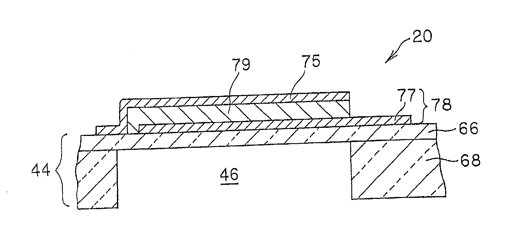
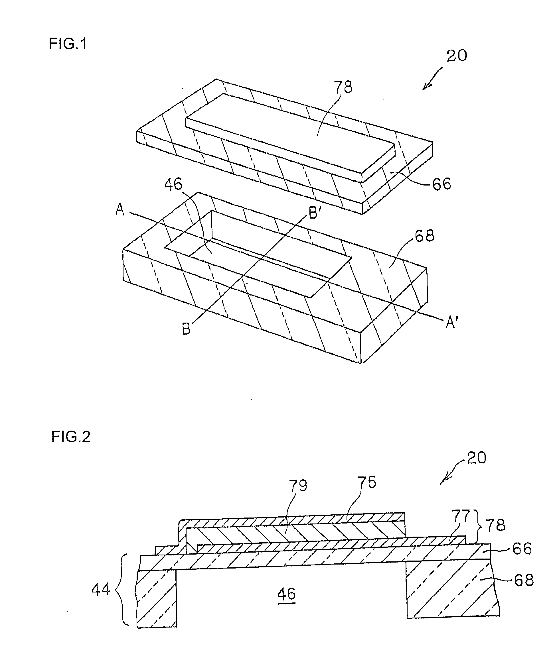
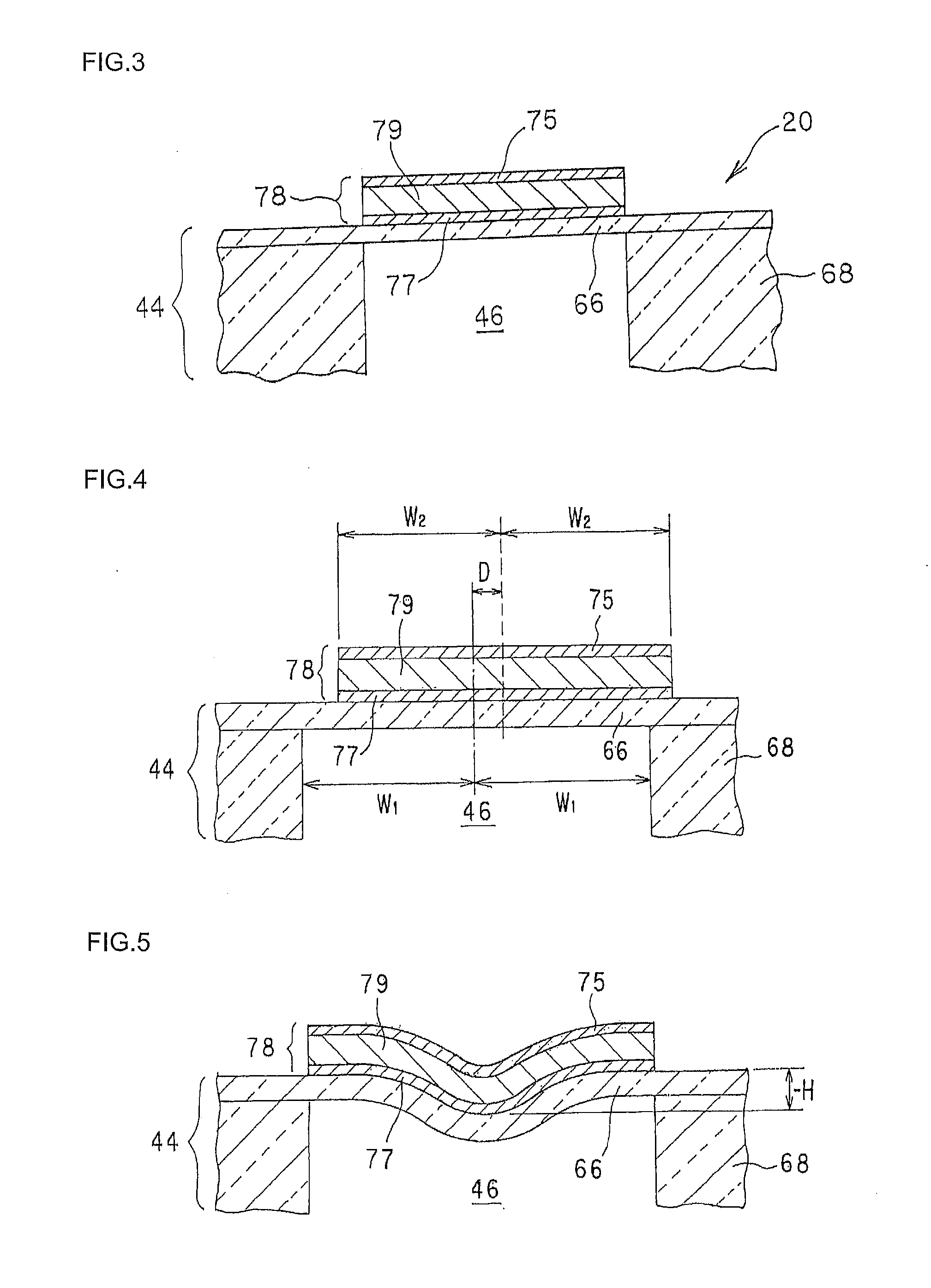
[0137]There was manufactured, as a piezoelectric / electrostrictive actuator before adjustment, a piezoelectric / electrostrictive actuator having the same structure as that of the piezoelectric / electrostrictive actuator 20 shown in FIGS. 1 to 3. The piezoelectric / electrostrictive actuator before adjustment was manufactured by the following method. In the first place, a binder, a solvent, a dispersant, and a plasticizer were mixed with zirconium oxide to prepare slurry. Next, the slurry was subjected to a defoaming treatment to manufacture a green sheet having a predetermined thickness by a reverse roll coater method. Then, the green sheet was processed by laser processing into a predetermined shape. After a plurality of green sheets were piled up in sequence, a ceramic green laminate body was obtained by pressure bonding with heat. The green sheet laminate body obtained was fired at a temperature of 1200 to 1600° C. to obtain the substrate (corresponding with the substrate 44 of FIGS. ...


PUM

PropertyMeasurementUnit
Diameteraaaaaaaaaa
Widthaaaaaaaaaa
Frequencyaaaaaaaaaa

Abstract

There is provided a method for testing a piezoelectric / electrostrictive actuator, wherein the displacement of a piezoelectric / electrostrictive actuator is estimated on the basis of the relations between one or more frequency characteristic values selected from the group consisting of the heights and areas of the peaks of the resonance waveforms and the difference of the maximum and minimum of the first order or first to higher orders of the resonance frequency characteristic values of the piezoelectric / electrostrictive actuator and the k-th order (k=1 to 4) of the first or first to higher orders of resonance frequencies. According to this piezoelectric / electrostrictive actuator testing method, a piezoelectric / electrostrictive actuator can be tested with high precision without actually driving the same as a product and without being accompanied by any disassembly / breakage.

Description

TECHNICAL FIELD[0001]The present invention relates to a method for testing a piezoelectric / electrostrictive device realizing high precision, a testing apparatus, and a method for adjusting a piezoelectric / electrostrictive device.BACKGROUND ART[0002]In recent years, there has been desired a displacement control device for adjusting an optical path length or a position by the submicron in fields of optics, precision machinery, semiconductor manufacturing, and the like. To respond to this, there has been promoting the development of piezoelectric / electrostrictive devices such as a piezoelectric / electrostrictive actuator utilizing strain based on the inverse piezoelectric effect, the electrostrictive effect, or the like caused when an electric field is applied to a ferroelectric body or an antiferroelectric body and a piezoelectric / electrostrictive sensor utilizing charge generation caused when stress is applied to a ferroelectric body / antiferroelectric body on the basis of a similar ef...

Claims


Application Information

Patent Timeline
IPC IPC(8): G01R31/01H01L41/22H01L41/04G01R31/28B23K26/38H01L41/253H01L41/257H01L41/39
CPCH01L41/253G01N29/12H01L41/29Y10T29/42G01N29/4454G01N2291/2697H01L41/047H01L41/0973Y10T29/49004H10N30/2047H10N30/04H10N30/06H10N30/87
Inventor GOTO, NAOKIOHNISHI, TAKAO
Owner NGK INSULATORS LTD
Learn More