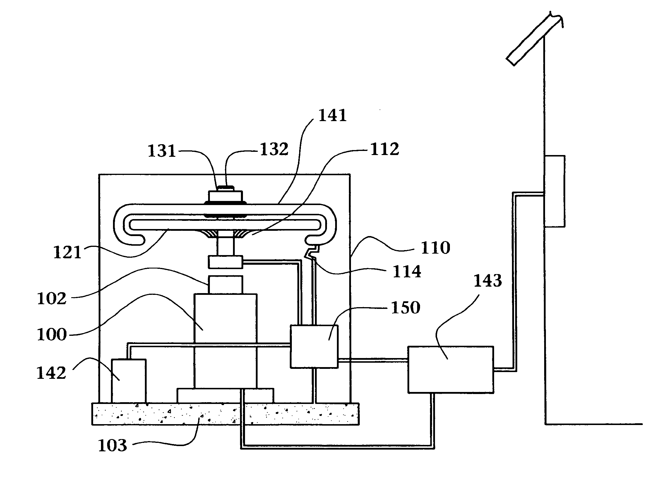
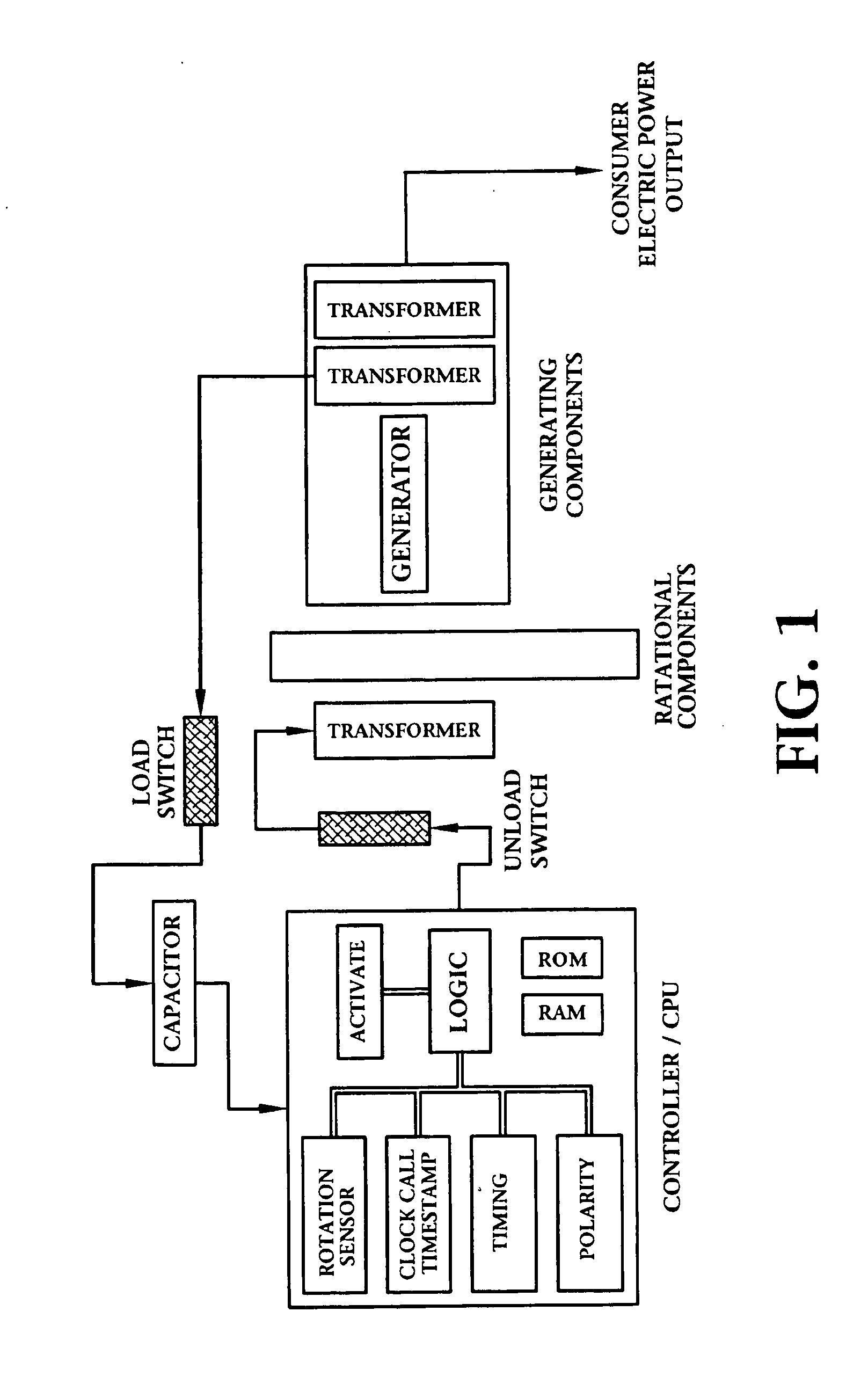
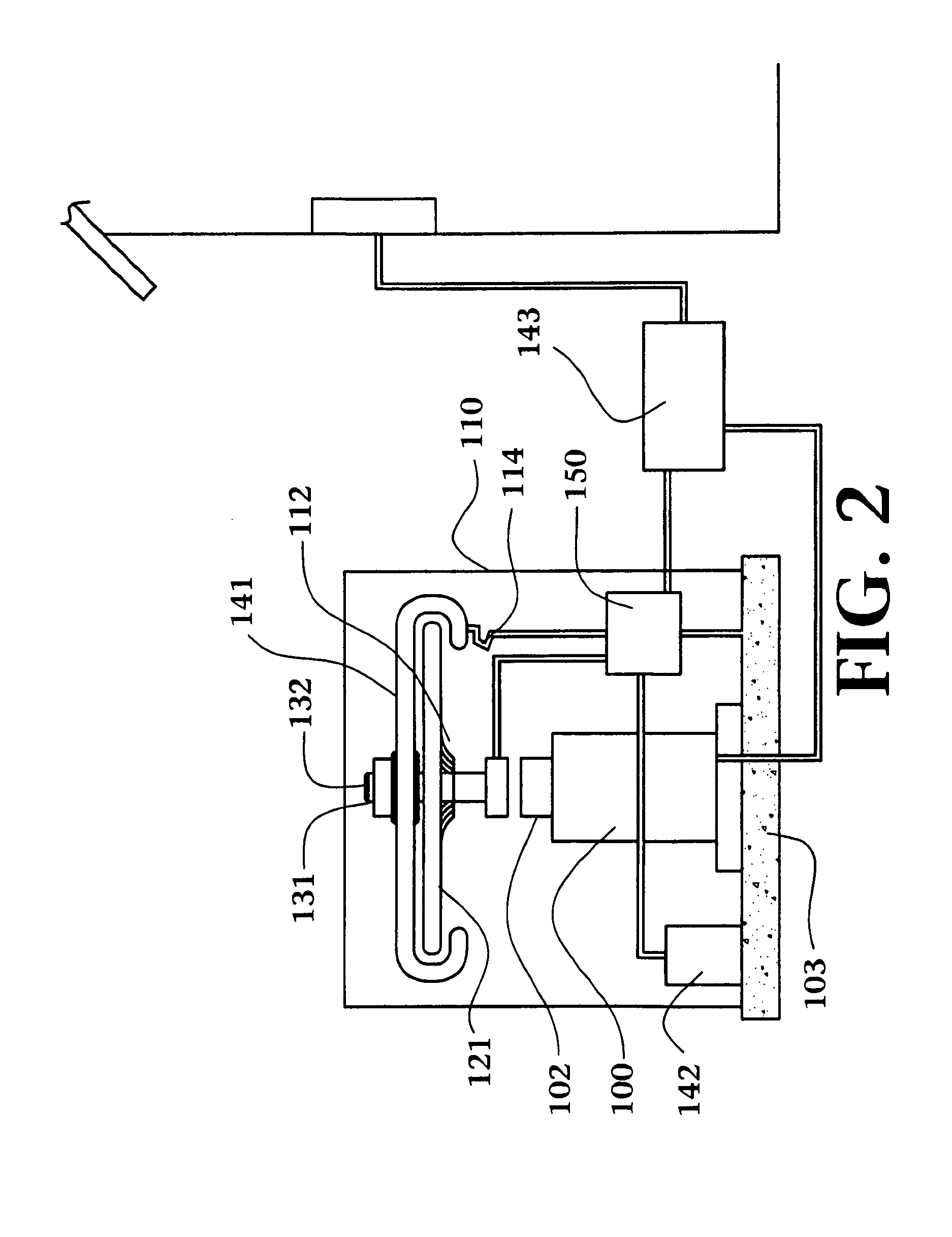
Electro-motive machine using halbach array and electrons trapped in electromagnetic providing current

a technology of electromagnetic providing current and electromagnet, which is applied in the direction of motor/generator/converter stopper, dynamo-electric converter control, etc., can solve the problems of consuming a relatively substantial effort in energizing the electromagnet, including specific limitations of the existing halbach array, and rapid reversal of the electromagnetic field associated with the stator

Active Publication Date: 2011-02-03
EPSTEIN MARTIN +1
View PDF7 Cites 3 Cited by
  • Summary
  • Abstract
  • Description
  • Claims
  • Application Information

AI Technical Summary

Benefits of technology

[0036]It is another object of the present invention to take advantage of the disparity which can be created in the magnetic properties of various materials to convert and generate consumable energy.
[0037]It is another object of the present invention to provide apparatus and method for producing and maintaining an alternative source of energy which is independent of fossil fuels and may, for some realistic period of time, be self-sustaining.
[0038]It is another object of the present invention to provide apparatus and method for producing and maintaining an alternative source of energy which considers and takes advantage of the behaviour of electrons within inductive circuits which are subject to rapidly changing and precisely controlled electromotive forces.

Problems solved by technology

It would appear that the rapid reversal of the electromagnetic fields associated with the stator consumes a relatively substantial effort in energizing the electromagnets and then loss as the electromagnet is de-energized in order to be reversed.
While each application must be specifically engineered, the research performed and published to date includes specific limitations of the existing Halbach-type array.

Method used


Image

  • Electro-motive machine using halbach array and electrons trapped in electromagnetic providing current
  • Electro-motive machine using halbach array and electrons trapped in electromagnetic providing current
  • Electro-motive machine using halbach array and electrons trapped in electromagnetic providing current

Examples


Embodiment Construction

s desired for energization.

[0056]Table 2 depicts the parameters burned into the device unique chip of the preferred embodiment of the present invention.

[0057]Table 3 depicts the parameters monitored by sensing and controlling software in signal communication with the device-unique chip of the preferred embodiment of the present invention.

[0058]Table 4 depicts a predicted efficiency model for a configuration of apparatus built according to the preferred embodiment of the present invention without a blocking circuit.

[0059]Table 5 demonstrates the improved efficiencies achieved with the present device.

[0060]Table 6 is an example of an algorithm which could be used to control the logic circuitry.

[0061]While certain drawings and tables have been provided in order to teach the principles and operation of the present invention, it should be understood that, in the detailed description which follows, reference may be made to components or apparatus which are not included in the drawings. Su...


PUM


Abstract

A Halbach array is radially disposed in an environment optimized for efficiency and controlled for efficient generation and use of power in order to generate, establish, and maintain a desired level of rotational energy with enhanced efficiency.

Description

[0001]This is a continuation part from U.S. Pat. No. 7,352,096 issued on Apr. 11, 2008.FIELD OF THE INVENTION[0002]The invention relates to the exploitation of electronic phenomena which may occur in devices and methods for the generation of rotational energy from a Halbach array for the production of electricity and other useful applications.BACKGROUND OF THE INVENTION[0003]Halbach magnetic arrays have enabled electrical motors to achieve substantial new efficiencies and powers than were previously possible. Various applications of these types of magnetic arrays have included such things as the bullet train, rotational electric batteries, and a variety other mechanical and electrical devices.[0004]Since the Halbach array was first developed it has been applied to various applications in order to exploit the relationship between kinetic and electrical energy which are uniquely related and can be transitioned by magnetic fields. For instance, in U.S. Pat. No. 6,758,146 issued to Post...

Claims


Application Information

Patent Timeline
Patent Type & Authority Applications(United States)
IPC IPC(8): H02P27/12H02K1/27H02K53/00
CPCH02K21/24H02K53/00H02K21/38
Inventor EPSTEIN, MARTINHARMS, JON ERIC
Owner EPSTEIN MARTIN
Why Eureka
Try Eureka