
Electric Power Steering System

a technology of electric power steering and steering wheel, which is applied in the direction of motor/generator/converter stopper, dynamo-electric converter control, electric devices, etc., can solve problems such as abnormalities, and achieve the effects of improving reliability, cost reduction, and reducing start-up tim

Inactive Publication Date: 2011-02-03
JTEKT CORP
View PDF10 Cites 21 Cited by
  • Summary
  • Abstract
  • Description
  • Claims
  • Application Information

AI Technical Summary

Benefits of technology

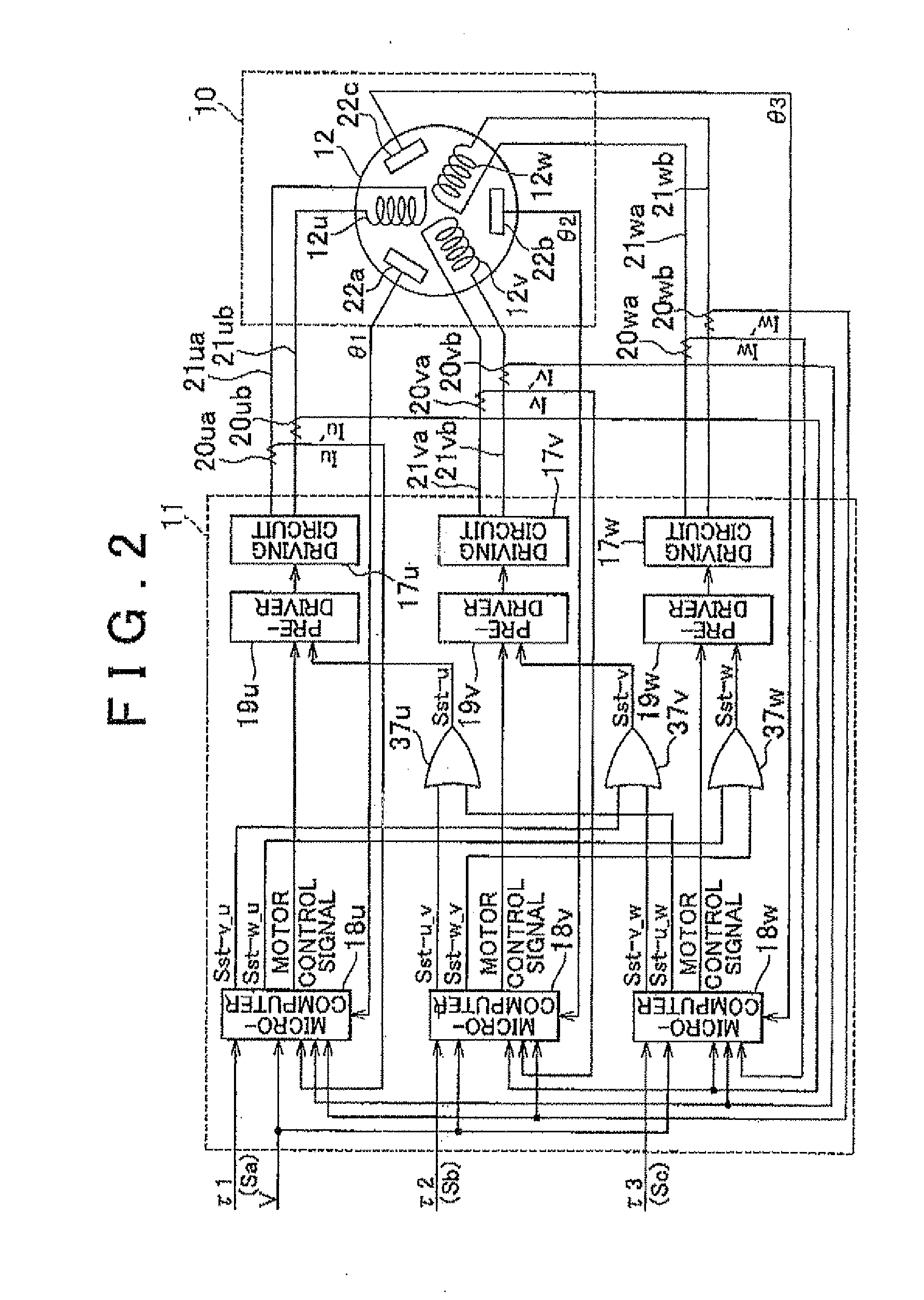
[0011]With the above arrangement, when some abnormality occurs in a control system of a certain phase, the abnormality appears in corresponding phase current command values calculated by the control signal generators, or corresponding phase current values of the motor generated through execution of the current feedback control. Accordingly, each of the control signal generators mutually monitors phase current deviations that appear in the phases other than the corresponding phase, so as to detect an abnormality that occurs in the phase(s) thus monitored. When two of the control signal generators both determine that an abnormality occurs in the remaining one phase, the controller confirms that the control system of the remaining phase is in an abnormal condition, thus assuring improved reliability.
[0012]In particular, when an abnormality that occurs in any of the control signal generators has an influence on power assist control, the abnormality appears in the form of a phase current deviation associated with the corresponding phase. Accordingly, other abnormality determination control concerning an electronic control unit that provides each control signal generator, such as an initial check of a memory upon start-up of the control unit as described above, may be eliminated, and may be replaced by the abnormality determination based on the current deviation in each phase. Consequently, not only the start-up time is reduced, but also cost reduction due to reduction of the processing power required of the control signal generators and reduction of the failure rate due to scale-down of relevant circuits can be achieved.

Problems solved by technology

In particular, when an abnormality that occurs in any of the control signal generators has an influence on power assist control, the abnormality appears in the form of a phase current deviation associated with the corresponding phase.

Method used


Image

  • Electric Power Steering System
  • Electric Power Steering System
  • Electric Power Steering System

Examples


Embodiment Construction

[0019]One embodiment of the invention will be described with reference to the drawings.

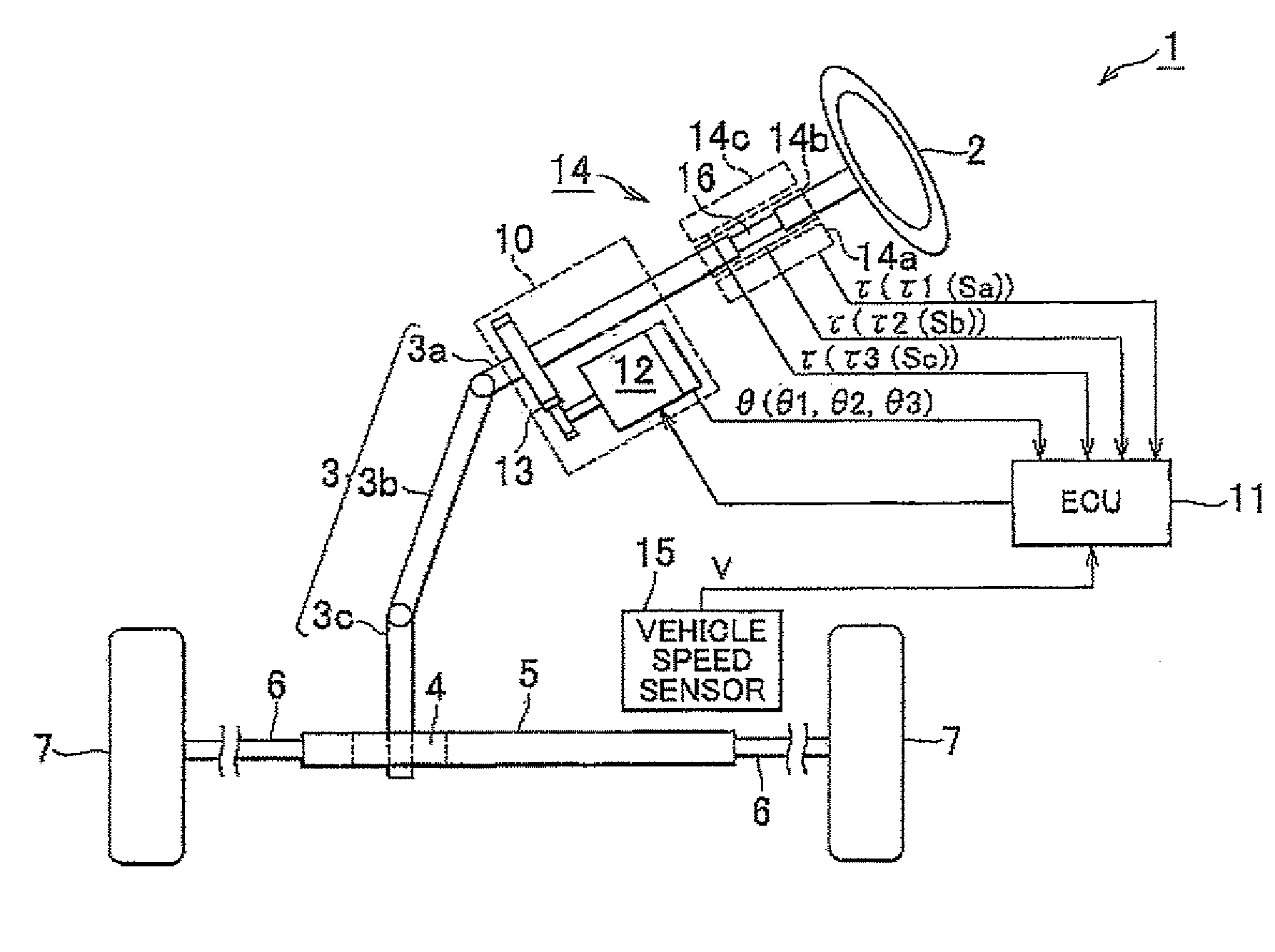
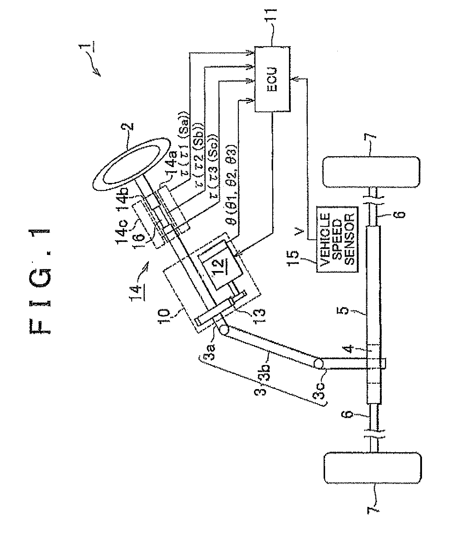
[0020]As shown in FIG. 1, in an electric power steering (EPS) system 1 of this embodiment, a steering shaft 3 to which a steering wheel 2 is fixed is coupled to a rack shaft 5 via a rack-and-pinion mechanism 4, and rotation of the steering shaft 3 caused by a steering operation is converted into reciprocating linear motion of the rack shaft 5 by means of the rack-and-pinion mechanism 4. The steering shaft 3 includes a column shaft 3a, an intermediate shaft 3b, and a pinion shaft 3c, which are coupled to each other. The reciprocating linear motion of the rack shaft 5 originating from the rotation of the steering shaft 3 is transmitted to knuckles (not shown) via tie rods 6 coupled to the opposite ends of the rack shaft 5, so as to change the turning angles of steerable wheels 7.

[0021]The EPS system 1 includes an EPS actuator 10 that serves as a steering force assist device for providing assist forc...


PUM


Abstract

In an electric power steering system, an ECU 11 that controls the operation of the system includes three independent microcomputers 18u, 18v, 18w that perform phase current feedback control with respect to the corresponding phases, so that sinusoidal current is applied to each phase of the motor 12 as a non-connected motor. Also, each of the microcomputers 18u, 18v, 18w monitors a deviation of an actual current value from a phase current command value, with respect to each of two phases other than the corresponding phase, and determines that an abnormality occurs in the phase in question when the deviation exceeds a predetermined threshold value. When two of the microcomputers 18u, 18v, 18w determine that the abnormality occurs in the remaining one phase, the ECU 11 confirms the determination that the phase in question is in an abnormal condition.

Description

INCORPORATION BY REFERENCE[0001]The disclosure of Japanese Patent Application No. 2009-175631 filed on Jul. 28, 2009, including the specification, drawings and abstract, is incorporated herein by reference in its entirety.BACKGROUND OF THE INVENTION[0002]1. Field of the Invention[0003]The invention relates to an electric power steering system.[0004]2. Description of the Related Art[0005]An electric power steering (EPS) system using a motor as a driving source has been proposed as one type of power steering systems for vehicles. The EPS system is characterized by a high degree of flexibility in the layout thereof and a small amount of energy consumption. In recent years, therefore, the electric power steering system has been increasingly employed in a wide variety of vehicle types, from compact vehicles to large vehicles.[0006]In the EPS system, numerous abnormality determining operations (diagnostics) are performed in information processing equipment (such as a microcomputer) that p...

Claims


Application Information

Patent Timeline
IPC IPC(8): H02H7/08B62D5/04B62D6/00B62D119/00H02P6/06H02P6/08H02P6/12H02P6/28
CPCB62D5/0403B62D5/046H02P6/085B62D5/0487B62D5/0484B60L3/0061B60L2220/54H02P2209/03Y02T10/64
Inventor URA, NORITAKE
Owner JTEKT CORP
Learn More