Magnetic rotary system for input devices

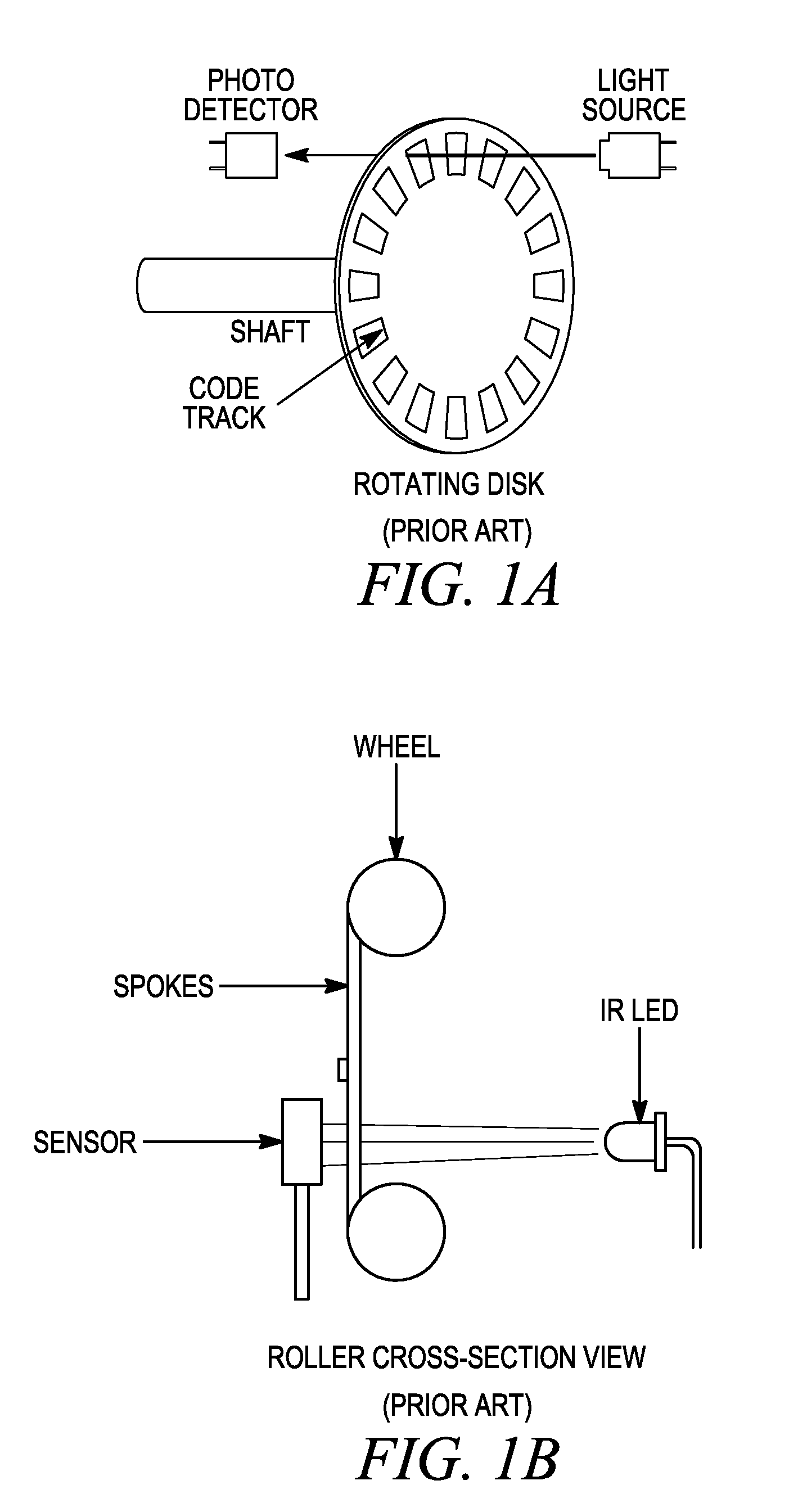
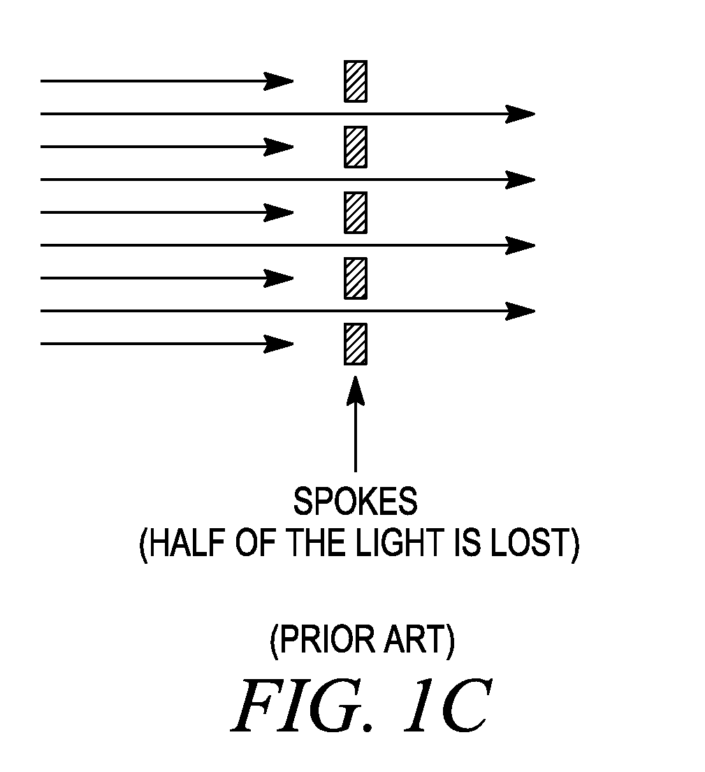
a magnetic encoder and input device technology, applied in the direction of converting sensor output, using electrical/magnetic means, instruments, etc., can solve the problems of power waste, large arrangement, and light loss when it hits the non-transparent parts of the wheel, etc., to achieve low cost, easy manufacturing, and relatively simple magnetization required

Inactive Publication Date: 2011-02-03
LOGITECH EURO SA
View PDF17 Cites 982 Cited by
  • Summary
  • Abstract
  • Description
  • Claims
  • Application Information

AI Technical Summary

Benefits of technology

In one embodiment, a magnet is attached to the roller. In one embodiment, the magnet is included inside the roller. A magnetic encoder provides information regarding the absolute angular position of the roller. It is to be noted that this is in contrast to the relative position information obtained in prior art rollers in pointing devices. Further, in one embodiment, the magnetization required is fairly simple, and is low cost. Moreover, tight tolerances are not required, and a system in accordance with an embodiment of the present invention is thus easy to manufacture.
As mentioned above, in one embodiment, the magnet is contained inside the wheel. In such a situation, the sensor is on one side of the wheel. In another embodiment, the magnet is attached to a side of the wheel, and the encoder / sensor is on the same side as the magnet. Components required for measuring the rotation of the wheel are only on one side of the wheel, thus leading to a much more compact assembly than conventional roller assemblies with components on both sides of the wheel for measuring rotation.
Further, since the sensor is a magnetic sensor, it can be covered by any non-ferromagnetic (non-metallic) material, without affecting its performance. Thus, in one embodiment, the sensor is covered (by a plastic case, for example) to protect it from dust and other foreign particles, without affecting the sensor's performance. Furthermore, in one embodiment, such casings also provide the encoder sensor being with electro-static discharge (ESD) protection, to reduce ESD issues.
In one embodiment, a ratcheting feel provided to the user when rotating the wheel is synchronized with the rotation signal sent by the wheel to the host. The user thus receives more coordinated and realistic feedback from the wheel.

Problems solved by technology

This leads to the requirement of a certain volume / space on both sides of the wheel, making the entire arrangement relatively large.
Second, since the light has to travel through the wheel to get to the sensor, part of the light is lost when it hits the non-transparent portions of the wheel (for example, the spokes of the wheel).
Since part of the light emitted by the light source is not received by the sensor, power is wasted.
Further, the wheel is relatively wide and this puts some distance between the light source and the sensor.
When the light source is an LED, the LED beam is divergent, and this results in a light intensity that decreases when the distance increases.
Other problems exist in conventional wheels in input devices.
When the wheel is tilted, the relative position of the wheel with respect to the beam changes, and thus the encoding of the motion of the wheel in the tilted position may be inaccurate.
Spurious counts of the wheel are often generated, and are very annoying for the users.
These additional components increase the cost, as well as require a large form factor.
Yet other problems exist with conventional wheels in input devices.
Requirements of such tight tolerances make the manufacture of pointing devices more difficult and expensive.
Still other issues relate to synchronizing the ratcheting feel received by the user when rotating the wheel, with the signal sent by the wheel to the host device.
Still another problem encountered in these prior art implementations is that only the relative position of the rotation of the wheel (the incremental rotational changes) are measured.
There are several issues with such incremental / relative measurement.
Such issues include that counts are lost, leading to loss of data, loss of correlation between counts and wheel position, and loss of ratchet synchronization.
However, some of the other problems described above remain, and some new ones are introduced.
Therefore with such conventional reflective encoders, half of the light energy is still lost, thus leading to power consumption issues, as with conventional transmissive encoders discussed above.
Further, several of the other issues outlined above are not resolved.
However, for various reasons, these ways have not been implemented in pointing devices.
However, this type of setup has not been used in pointing devices for several reasons.
One reason is that such assemblies are expensive—it is expensive to magnetize multi-pole magnets.
Another reason is that it is very difficult to accommodate so many magnetic poles in a small magnet, thus leading to a form factor that is too large to be desirable for implementations in devices with small for factors.
However, such implementations are also not suitable for use in rollers in pointing devices for several reasons.
One reason is that such implementations require large power consumption, which is not acceptable in pointing devices, especially in wireless ones which are becoming increasingly common.
Another reason is that such configurations cannot measure the absolute position with a resolution as great as that required in pointing device implementations.
In such systems, a resolution of better than one degree typically cannot be achieved.
However, these implementations are again not suitable for use in rollers in pointing devices for several reasons.
One reason is that very accurate mechanical alignment is required for such implementations, and such tight tolerances are very difficult to achieve during manufacture of pointing devices.

Method used


Image

  • Magnetic rotary system for input devices
  • Magnetic rotary system for input devices
  • Magnetic rotary system for input devices

Examples


Embodiment Construction

The figures (or drawings) depict a preferred embodiment of the present invention for purposes of illustration only. It is noted that similar or like reference numbers in the figures may indicate similar or like functionality. One of skill in the art will readily recognize from the following discussion that alternative embodiments of the structures and methods disclosed herein may be employed without departing from the principles of the invention(s) herein.

It is to be noted that the terms “wheel” and “roller” are used interchangeably herein. It is further to be noted that while most of the discussion here focuses on wheels in input devices, the present invention is not limited to such embodiments. Embodiments of the present invention can be used in input mechanisms in other devices which use angular movement. Examples include, but are not limited to, dials such as volume dials, buttons like digital potentiometers, tuning buttons, etc. It is to be noted that although the following des...


PUM

PropertyMeasurementUnit
magnetic fieldaaaaaaaaaa
distanceaaaaaaaaaa
distanceaaaaaaaaaa

Abstract

Embodiments of the present invention include a roller for an input device, where the roller's absolute angular position is measured by a magnetic encoder. A magnet is attached to the roller, possibly inside the roller so as to make the embodiment more compact. In one embodiment, the magnetization is simple and low cost. Further, tight tolerances are not required, and such a system is easy to manufacture. In one embodiment, the sensor is covered by any non-ferromagnetic material, to protect it from foreign particles, and to reduce ESD. In one embodiment, the wheel consumes much less power than conventional wheels in input devices. In one embodiment, the tilting of the wheel is measured using the same sensor that is used for measuring the rotation of the wheel. In one embodiment, a ratcheting feel provided to the user when rotating the wheel is synchronized with the rotation signal.

Description

BACKGROUND OF THE INVENTION1. Field of the InventionThe present invention relates generally to an improved roller using magnetic encoders, and more particularly, to rollers using magnetic encoders in an input device, such as a mouse.2. Description of the Related ArtsInput devices, such as a mouse or a trackball, are well-known peripherals for personal computers and workstations. Such input devices (or pointing devices) allow rapid relocation of the cursor on a display screen, and are useful in many text, database and graphical programs. Perhaps the most common form of pointing devices is the electronic mouse.Most mice include several buttons (e.g., left click button, right click button, etc.), as well as a wheel / roller. Such a wheel is turned by a user's finger, and the rotation of such a wheel is measured and translated into various inputs such as scrolling through a document on the display associated with a host to which the mouse is coupled, zooming in / out in applications on the ...

Claims


Application Information

Patent Timeline
Patent Type & Authority Applications(United States)
IPC IPC(8): G01B7/30H05K13/04
CPCG01D5/145G06F1/3215G06F3/0362Y10T29/49826G01B7/30Y10T29/5313B23P19/04
Inventor CHAUVIN, NICOLASTHEYTAZ, OLIVIER
Owner LOGITECH EURO SA
Why Eureka
Try Eureka