Onboard radio communication system

Inactive Publication Date: 2011-02-03
MITSUBISHI ELECTRIC CORP
View PDF12 Cites 29 Cited by
  • Summary
  • Abstract
  • Description
  • Claims
  • Application Information

AI Technical Summary

Benefits of technology

According to the onboard radio communication system in accordance with the present invention, even if the vehicle containing the onboard radio communication system

Problems solved by technology

In the vehicle where the individual radio communication systems mentioned above are mixed, if radio systems using nearby frequency bands are mixed in particular, it is likel

Method used


Image

  • Onboard radio communication system
  • Onboard radio communication system
  • Onboard radio communication system

Examples


embodiment 1

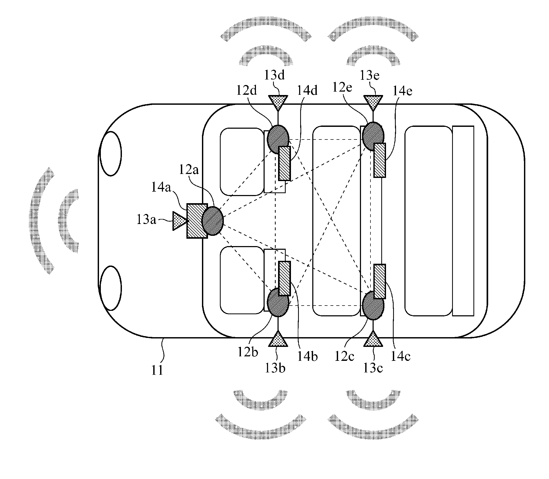
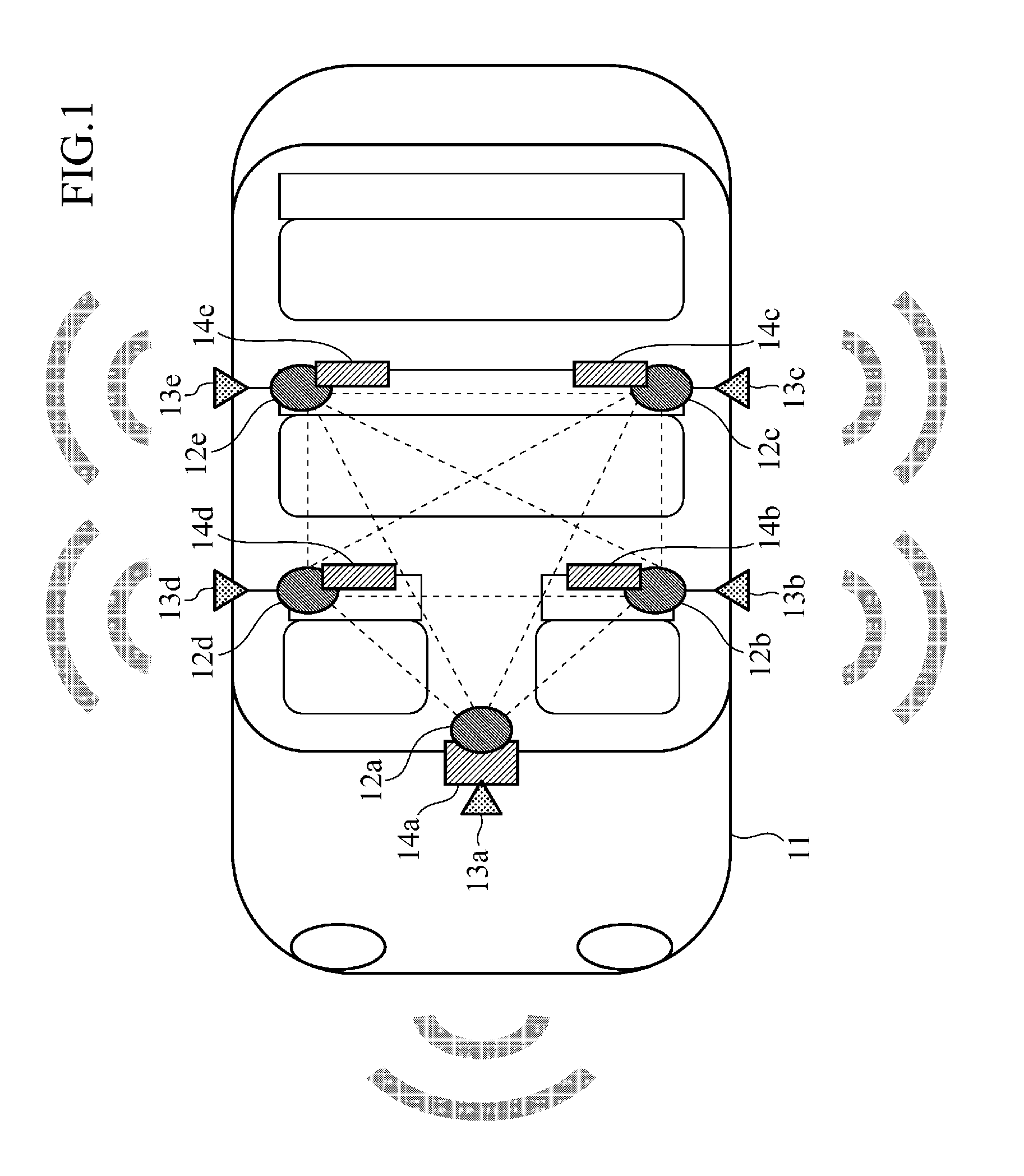
FIG. 1 is a diagram showing a system configuration of an onboard radio communication system of an embodiment 1 in accordance with the present invention. As shown in FIG. 1, the onboard radio communication system of the embodiment 1 in accordance with the present invention comprises a vehicle itself 11, and a plurality of radio sets 12a-12e arranged in the vehicle, ultrasonic sensors 13a-13e, for example, for detecting an adjacent vehicle, and onboard information devices 14a-14e.

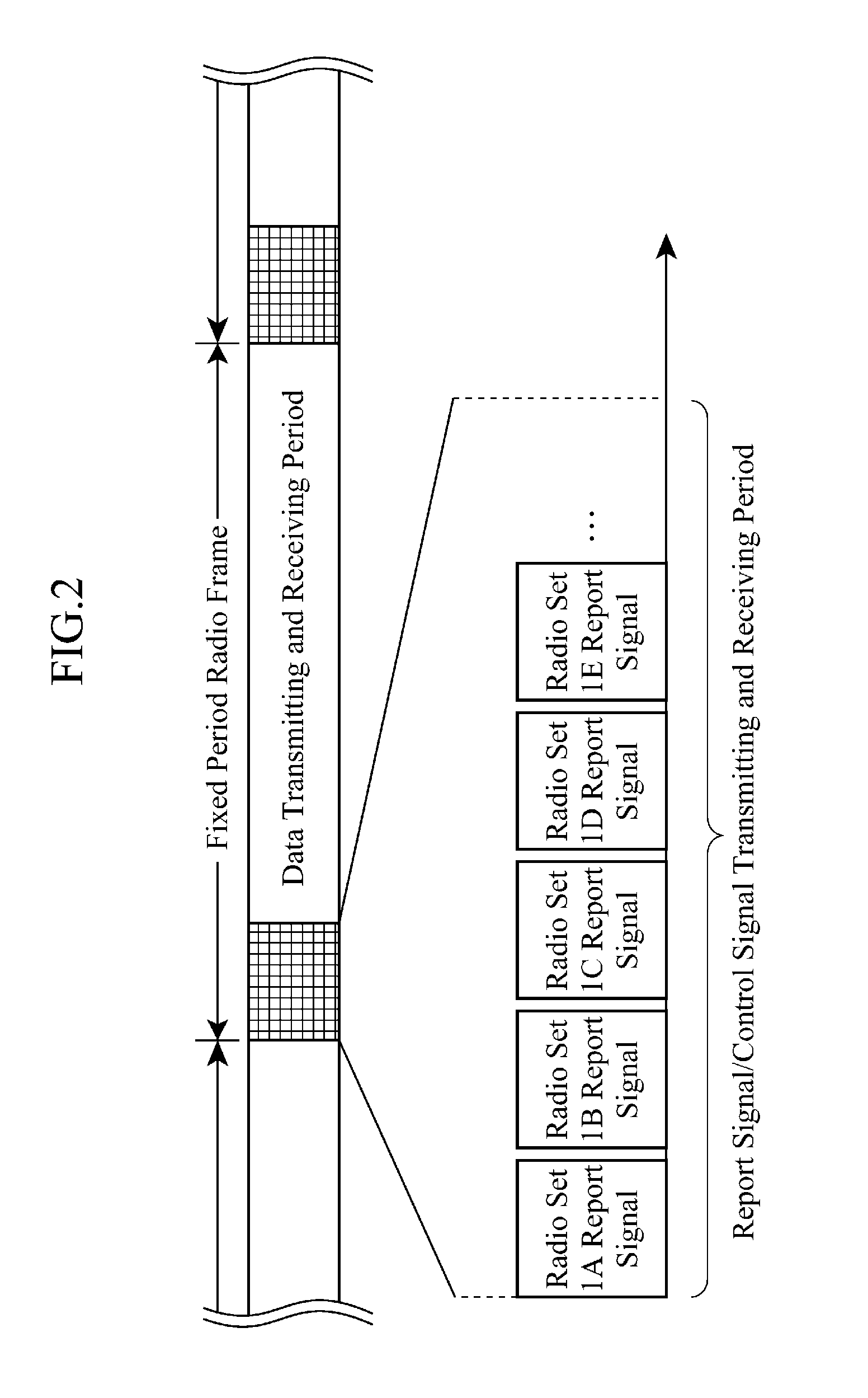
The radio sets 12a-12e carry out communications between them by transmitting and receiving radio signals. Each of the radio sets 12a-12e achieves timing synchronization on a fixed-period frame basis as in FIG. 2 which shows a structural example of a radio communication frame. In addition, to a fixed period at the head of the frame, report signals 1A-1E are assigned for delivering state management information about them to the radio sets 12a-12e constituting the radio network, and control signals are assigned...

embodiment 2

FIG. 8 is a diagram showing a system configuration of an onboard radio communication system of an embodiment 2 in accordance with the present invention.

As shown in FIG. 8, the onboard radio communication system of the embodiment 2 in accordance with the present invention differs from the embodiment 1 shown in FIG. 1 in that the detection information items from the ultrasonic sensors 13a-13e are gathered into a single radio set (radio set 12a, here), and the radio set 12a delivers the adjacent vehicle detection information to the other radio sets 12b-12e using the report signals.

Then, as for selecting a radio set (one of 12a-12e) for carrying out interference detection of radio waves, and causing the radio set selected (one of 12a-12e) to control and execute the radio interference detection using the control signals, the embodiment 2 is the same as the embodiment 1. The set carrying out the interference detection of the radio wave, the radio set 12b, for example, reports the radio in...

embodiment 3

FIG. 9 is a diagram showing a system configuration of an onboard radio communication system of an embodiment 3 in accordance with the present invention.

As shown in FIG. 9, the onboard radio communication system of the embodiment 3 in accordance with the present invention differs from the embodiment 1 or 2 in that its ultrasonic sensors 13a-13e operating as the adjacent vehicle detection unit have radio sets 31a-31e for communications.

Thus, as for the adjacent vehicle detection information, since the fellow radio sets (12a-31a, 12b-31b, . . . , 12e-31e) can transmit it between them, wiring becomes unnecessary, thereby being able to compactify the vehicle mounting space. As for the reporting of the position information about the adjacent vehicle via the report signals, and as for the radio interference detection and the switching control of the frequency channels, they are the same as those of the embodiment 1 or 2.

According to the onboard radio communication system of the embodiment ...


PUM


Abstract

Individual radio sets 12a-12e constituting an onboard radio communication system operate together with an adjacent vehicle detection unit (ultrasonic sensors 13a-13e) for detecting a second vehicle adjacent to a first vehicle 11. When it detects the adjacent vehicle, a radio interference decision unit constituting the radio sets 12a-12e decides radio interference due to an onboard radio communication system with the same radio scheme. When it detects the radio interference, a frequency channel switching unit constituting the radio sets 12a-12e switches the frequency channel to be used to avoid the interference of the radio waves.

Description

TECHNICAL FIELDThe present invention relates to an onboard radio communication system constituting a radio network having a plurality of radio sets arranged in a vehicle for transmitting and receiving radio signals.BACKGROUND ARTRecently, onboard information devices that have been developed centering on car navigation systems provide user applications having a variety of radio techniques.As typical examples of them, a lot of radio communication systems can be mentioned: a system for detecting the vehicle position using a GPS (Global Positioning System), radio beacon or the like; a system for receiving a broadcast such as radio / television; a system for paying a toll using an ETC (Electronic Toll Collection System); a communication system such as a mobile phone and wireless LAN (Local Area Network) for making external communications; and a local radio communication system such as a Bluetooth (registered trademark) for connecting between a user device and an onboard information device....

Claims


Application Information

Patent Timeline
IPC IPC(8): H04W64/00G01C21/26H04W16/14H04W56/00H04W72/08
CPCH04B15/04H04B2215/065H04W72/082H04W72/02H04W72/0406H04W28/04H04W72/20H04W72/541
Inventor HOSHIHARA, YASUNORITANAKA, KAZUYUKINISHIYAMA, KINICHIRO
Owner MITSUBISHI ELECTRIC CORP
Why Eureka
Try Eureka