Quick-heating of a urea supply conduit for an engine exhaust after-treatment system

a technology of urea supply conduit and after-treatment system, which is applied in the direction of machines/engines, mechanical equipment, electric control, etc., can solve the problems of poor after-treatment system performance, reduced effectiveness, and slushy, and achieve the effect of efficient transfer of engine coolant heat and accelerating the thawing of frozen solution

Inactive Publication Date: 2011-02-10
INT ENGINE INTPROP CO LLC
View PDF5 Cites 29 Cited by
  • Summary
  • Abstract
  • Description
  • Claims
  • Application Information

AI Technical Summary

Benefits of technology

[0013]The invention is effective to more efficiently transfer engine coolant heat to dosing fluid, thereby accelerating the thawing of frozen solution in sub-freezing ambient temperatures, an important factor for achieving compliance of an after-treatment system with relevant governmental regulations.

Problems solved by technology

Incomplete evaporation can lead to undesired consequences such as the formation of solid deposits in the exhaust system and poor performance of the after-treatment system.
In cold ambient temperatures near and below about 12° F., the solution in the tank, the pump, and associated conduits can freeze while in torrid ambient temperatures, the solution can become slush, significantly reducing its effectiveness when injected into the after-treatment system.

Method used


Image

  • Quick-heating of a urea supply conduit for an engine exhaust after-treatment system
  • Quick-heating of a urea supply conduit for an engine exhaust after-treatment system

Examples


Embodiment Construction

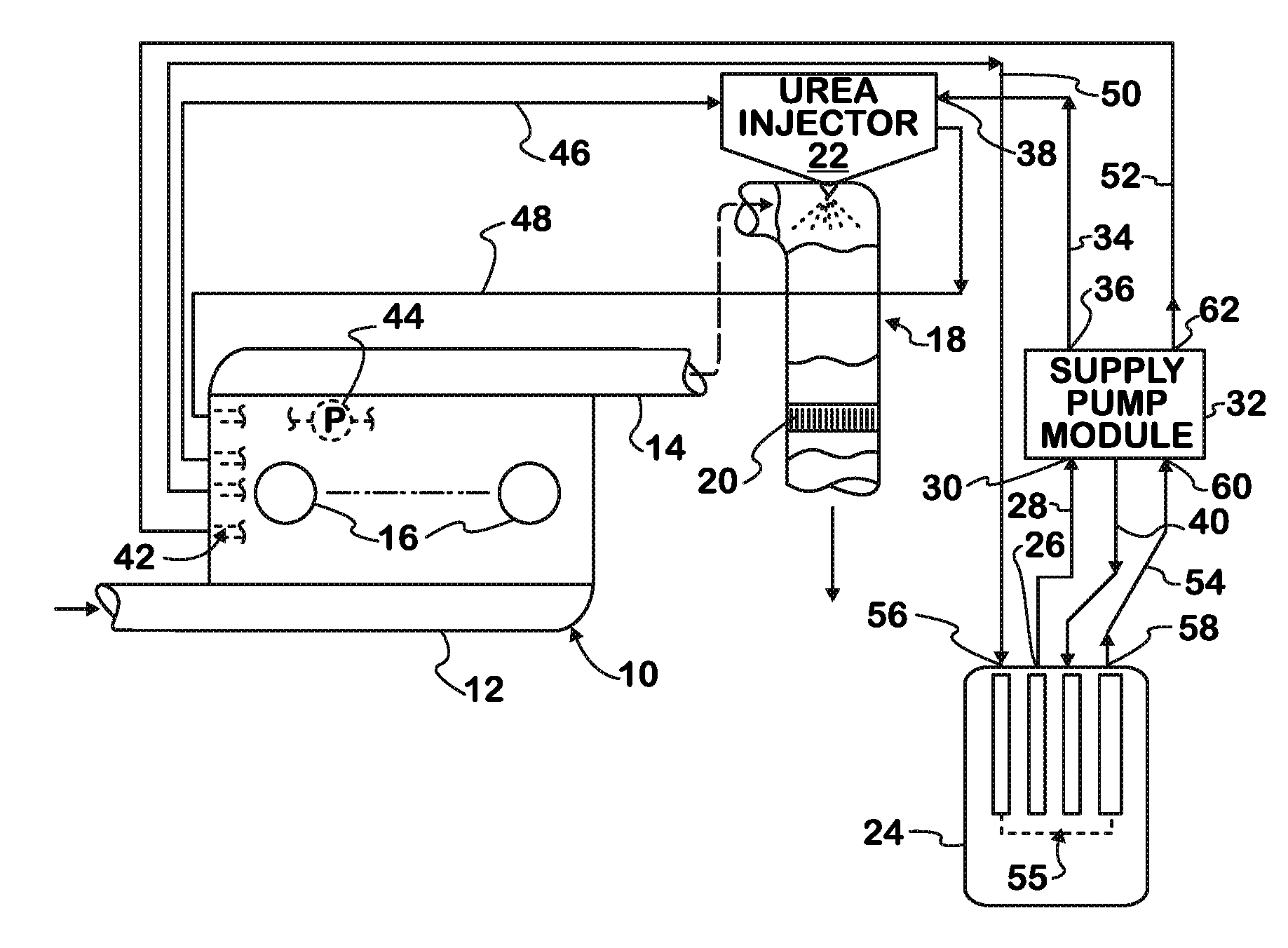
[0027]FIG. 1 shows a diesel engine 10 comprising an intake system 12 through which charge air enters and an exhaust system 14 through which exhaust gas resulting combustion exits, not all details of those two systems that are typically present being shown. Engine 10 comprises a number of cylinders 16 forming combustion chambers into which fuel is injected by fuel injectors to combust with the charge air that has entered through intake system 12. Energy released by combustion powers the engine via pistons connected to a crankshaft. When used to propel a motor vehicle, such as a truck, engine 10 is coupled through a drivetrain to driven wheels that propel the vehicle. Intake valves control the admission of charge air into cylinders 16, and exhaust valves control the outflow of exhaust gas through exhaust system 14 and ultimately to atmosphere. Before entering the atmosphere however, the exhaust gas is treated by one or more after-treatment devices in an after-treatment system 18.

[0028...


PUM


Abstract

A urea supply conduit (68) has a wall of good thermal conductivity. Urea solution in liquid phase is sucked out of a tank (24) through conduit (68) and delivered to a point of use (22) in an engine exhaust after-treatment system (18) through which products of combustion are conveyed from engine combustion chambers (16) to atmosphere. Liquid engine coolant is circulated through a coolant conduit (66) that has a wall of good thermal conductivity placed side-by-side and in physical association with the urea supply conduit wall to form a thermal conduction path for heat transfer between coolant in the coolant conduit and urea in the urea supply conduit, more quickly thawing any frozen urea.

Description

FIELD OF THE INVENTION[0001]This invention relates to internal combustion engines, especially motor vehicle engines that utilize urea dosing for after-treatment of engine exhaust.BACKGROUND OF THE INVENTION[0002]The performance of a diesel engine after-treatment system in converting NOx to other chemical products by selective catalytic reduction (SCR) relies on the presence of ammonia in the exhaust stream. Dosing engine exhaust by injection of aqueous urea, an ammonia-based reductant, into the exhaust stream at a location upstream of an SCR catalyst is one way to introduce ammonia into the exhaust system.[0003]For promptly commencing the conversion of NOx in engine exhaust gas to other chemical products through catalytic action upon engine starting, a urea dosing system needs to become effective in as short a time as possible. A known design practice places a urea injector at a location in the engine exhaust system where it can spray urea solution into the exhaust stream ahead of t...

Claims


Application Information

Patent Timeline
Patent Type & Authority Applications(United States)
IPC IPC(8): F02D45/00F01P5/10F01N3/10
CPCF01N3/2066F01N2610/10Y02T10/24F01P11/04F01P2060/18F01N2610/1406Y02T10/12
Inventor MAKARTCHOUK, ANDREILACK, ADAM C.
Owner INT ENGINE INTPROP CO LLC
Why Eureka
Try Eureka