
Flow soldering apparatus and flow soldering method

a flow soldering and flow soldering technology, applied in the direction of non-electric welding apparatus, soldering apparatus, manufacturing tools, etc., can solve the problems of poor soldering quality, inability to clean the soldering surface, photochemical smog, etc., to suppress the occurrence of soldering defects, good soldering quality, and the effect of adjusting the preheating profil

Inactive Publication Date: 2011-02-10
PANASONIC CORP
View PDF5 Cites 12 Cited by
  • Summary
  • Abstract
  • Description
  • Claims
  • Application Information

AI Technical Summary

Benefits of technology

[0026]According to the desirable modes of the present invention, it is possible to judge soldering quality, from the residual water content value on the surface of the substrate forming the work object, on the basis of the correlation between the residual water content value in the through holes of a sample substrate and the residual water content value on the surface of the sample substrate. Consequently, it is possible to remove a substrate having defective soldering quality, from the flow soldering line. Moreover, it is also possible to adjust the preheating profile. Consequently, even if VOC-free flux or low-VOC flux is applied to an electronic circuit substrate, it is possible to suppress the occurrence of soldering defects and hence good soldering quality is ensured.

Problems solved by technology

If preheating is not carried out, then the soldering surface is not cleaned.
If this solvent remains on the soldering surface of the electronic circuit substrate, then soldering of good quality cannot be achieved.
However, if a volatile organic compound (VOC) such as alcohol escapes into the atmosphere, then the volatile organic compound is decomposed by ultraviolet energy, or the like, and creates radicals.
These radicals are a cause of photochemical smog, or the like.
The water used as a solvent is difficult to remove completely before the molten solder makes contact with the electronic circuit substrate, at a preheating temperature of 100 to 150 degrees C. Consequently, when molten solder having a high temperature is applied by the jet solder tank onto the electronic circuit substrate onto which the VOC-free flux or low-VOC flux has been coated, problems arise, such as the occurrence of solder balls, solder wetting defects, solder bridging, or the like.
Consequently, if VOC-free flux or low-VOC flux is applied, then it has not been possible to obtain a finish equivalent to that obtained when VOC flux which uses an alcohol as the solvent is applied.
Incidentally, it is difficult to remove completely the water content in the through holes of the electronic circuit substrate, and even if the surface of the electronic circuit substrate is dried, moisture remains in the through holes.
However, until now, the preheating profiles of flow soldering apparatuses have not been set by taking account of the moisture in the through holes.
Consequently, with the flow soldering apparatuses described above, there is a risk that soldering defects may occur.
The flow soldering apparatuses described above are not able to determine the amount of water contained in the electronic circuit substrate which is the work object.
Hence, there is a risk that due to variations of this kind, an electronic circuit substrate from which the water content has not been removed sufficiently may be conveyed into the jet solder tank.
Consequently, with the flow soldering apparatuses described above, there is a risk that soldering defects may occur.

Method used


Image

  • Flow soldering apparatus and flow soldering method
  • Flow soldering apparatus and flow soldering method
  • Flow soldering apparatus and flow soldering method

Examples


Embodiment Construction

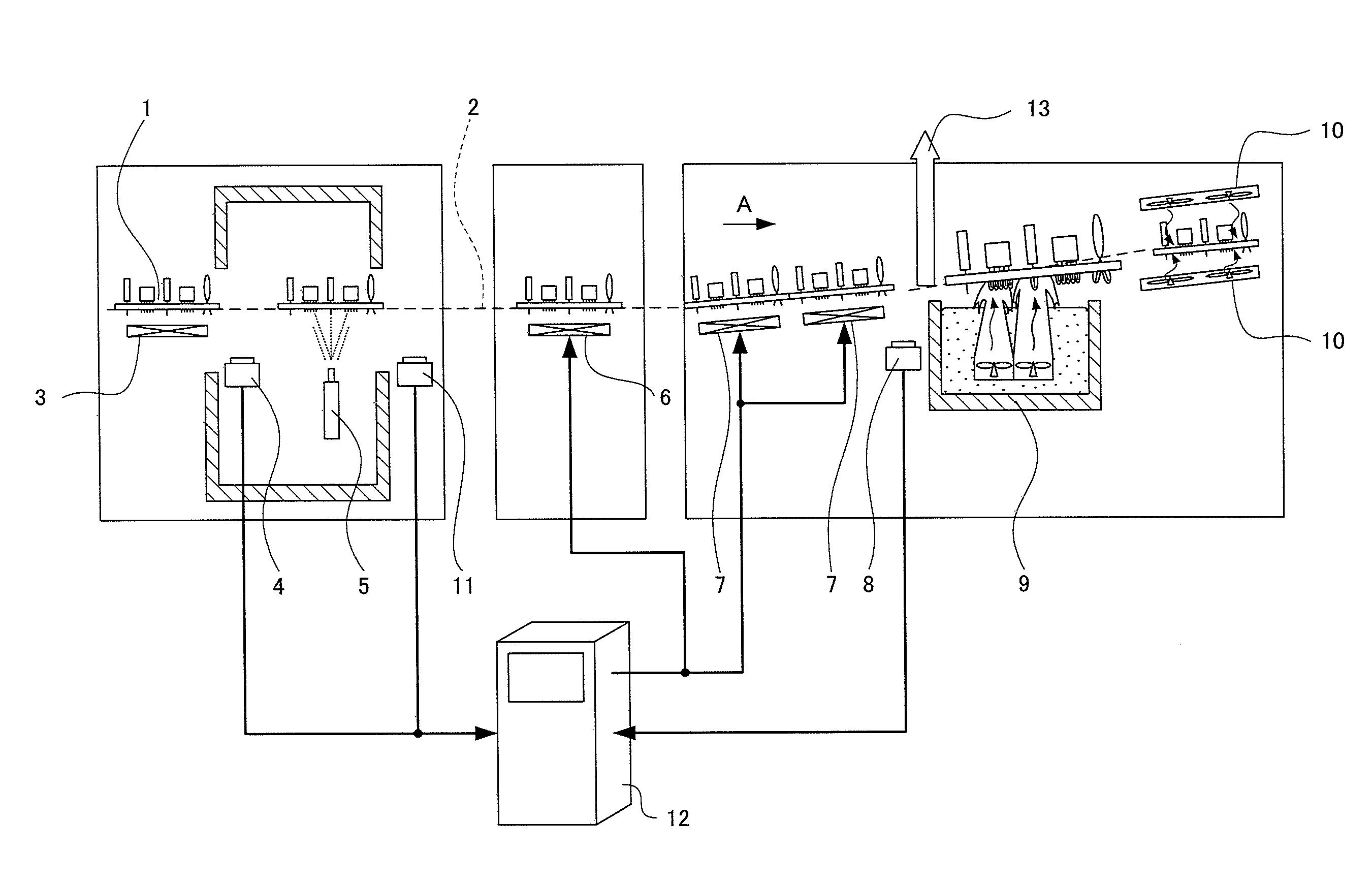
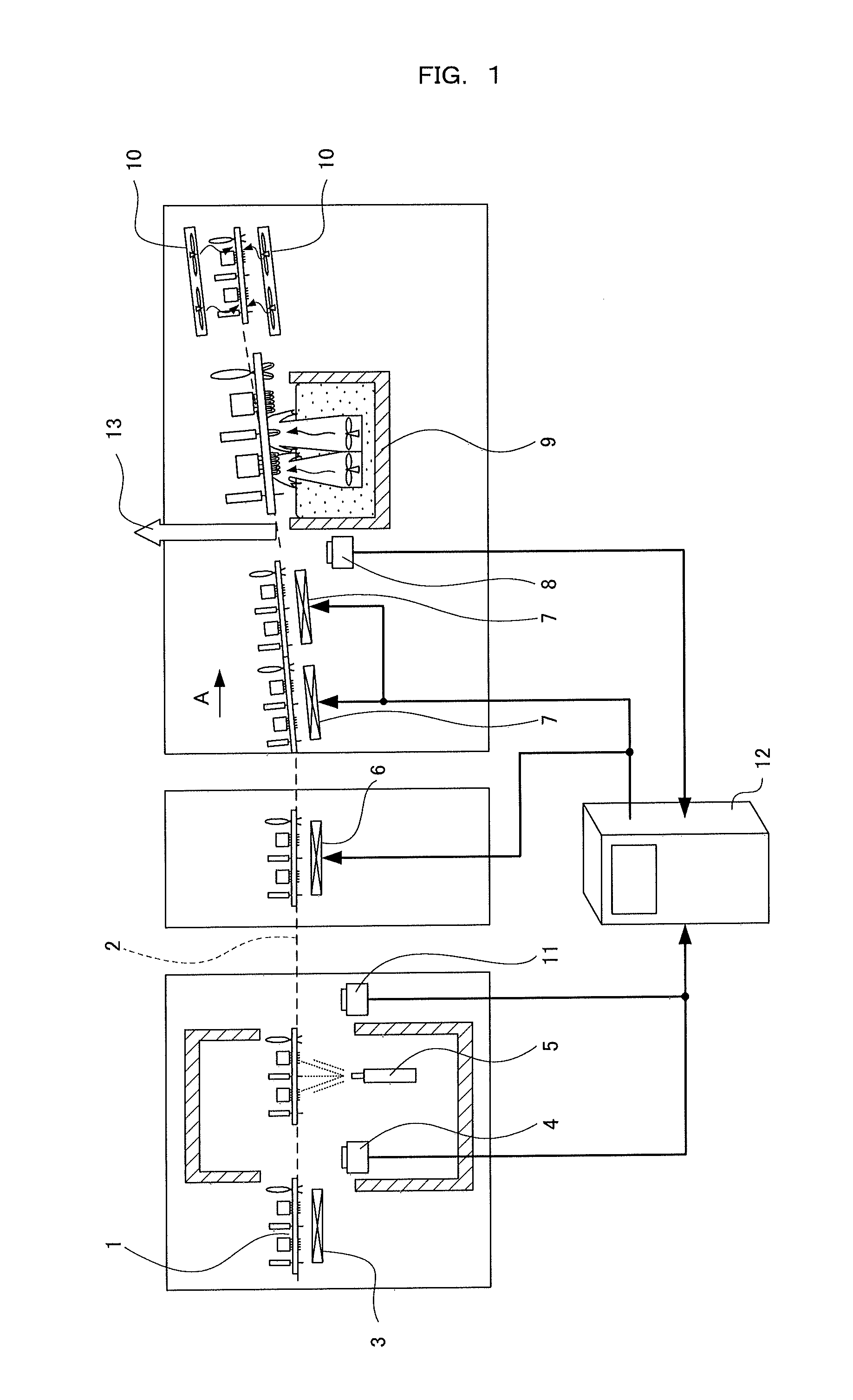
[0039]FIG. 1 is a diagram showing one example of the composition of a flow soldering apparatus according to an embodiment of the present invention. A water content sensor is incorporated into the flow soldering line, and the preheating profile is controlled by feedback control on the basis of a signal supplied from the water content sensor. Firstly, an overview of the composition of the present flow soldering apparatus is described.

[0040]As shown in FIG. 1, an electronic circuit substrate 1 formed with a plurality of through holes is introduced into this flow soldering apparatus. An electronic component is mounted previously onto the component surface of the electronic circuit substrate 1 which is introduced into the apparatus. The leads of the electronic component mounted on the substrate are inserted into the through holes of the electronic circuit substrate 1 and project from the soldering surface.

[0041]A conveyor 2 is provided in the flow soldering apparatus for conveying the in...


PUM

PropertyMeasurementUnit
through hole diameteraaaaaaaaaa
thicknessaaaaaaaaaa
diameteraaaaaaaaaa

Abstract

The present invention provides a flow soldering apparatus that can suppress the occurrence of soldering defects, even if VOC-free flux or low-VOC flux is applied to an electronic circuit substrate. In other words, the flow soldering apparatus according to the present invention includes: a water content sensor for measuring a residual water content of a surface of a substrate; and a monitoring device for judging whether soldering quality is satisfactory or not by using a residual water content value of the surface of the substrate acquired from the residual water content measured by the water content sensor, on the basis of a correlation between a residual water content value of a surface of a sample substrate and a residual water content value of through holes of the sample substrate, as acquired previously by using a plurality of substrate samples.

Description

TECHNICAL FIELD[0001]The present invention relates to a flow soldering apparatus and flow soldering method suitable for VOC-free flux or low-VOC flux. VOC is an abbreviation of Volatile Organic Compounds.BACKGROUND ART[0002]Flow soldering is a technology for soldering electronic components onto an electronic circuit substrate. An overview of this is explained below. Firstly, the electronic components are mounted on one main surface of the electronic circuit substrate. The leads of the mounted electronic component are inserted into through holes in the electronic circuit substrate and project out from the other main surface of the electronic circuit substrate. Molten solder makes contact with the surface where the leads project, thereby soldering the electronic component to the electronic circuit substrate. Below, one of main surfaces where the electronic component is mounted is called the component surface and the other one of main surfaces with which molten solder makes contact is ...

Claims


Application Information

Patent Timeline
Patent Type & Authority Applications(United States)
IPC IPC(8): B23K1/19B23K31/12B23K1/20
CPCB23K3/0653H05K3/3447H05K3/3468H05K2203/163H05K2201/10151H05K2203/0126H05K2203/111H05K3/3489
Inventor NAKAYA, KIMIAKISUETSUGU, KENICHIROKISHI, ARATA
Owner PANASONIC CORP
Learn More