
Annuloplasty tubes

Inactive Publication Date: 2011-02-10
ASHE KASSEM
View PDF7 Cites 1 Cited by
  • Summary
  • Abstract
  • Description
  • Claims
  • Application Information

AI Technical Summary

Benefits of technology

[0021]It is further object of the present invention to provide an annuloplasty tube that induces effective coaption of the anterior and posterior leaflets on the newly formed mitral valve annulus.
[0030]It is further object of the present invention to have a height adjustable means built in the annuloplasty tube, so that the height of the tube can be adjusted immediately during the operation.

Problems solved by technology

However, any dysfunction of any of the above mentioned sections of the mitral valve can cause mitral regurgitation or the abnormal leaking of the blood through the mitral valve from the left ventricle into the left atrium of the heart.
This is due to a genetic abnormality that results in a defect in the collagen that makes up the mitral valve.
This causes the valve leaflets to prolapse into the left atrium, thereby causing mitral regurgitation.
As noted earlier, diseases or certain natural defects of a heart valve, may impair the full closure of the valve, resulting in regurgitation.
For example, certain diseases may cause the dilation of the heart valve annulus, resulting in the distortion of the heart valve geometry or the shape of the valve.
This results in an ineffective closure of the mitral valve during ventricular contraction, leading to regurgitation or leakage.
There are a number of disadvantages in using these rings in annuloplasty.
One is that if a rigid annuloplasty ring is used in the surgery, the shape of the mitral valve becomes rigid and loses its natural and needed inflexibility.
This shortening, results in a phasic narrowing of mitral valve opening.
A semi flexible or combination of rigid / flexible rings cannot retain their flexibility after few months or years after the annuloplasty.
This loss of flexibility disrupts the normal flexing movement of the left ventricle resulting in complications of the heart.
Although, this operation is possible, it is very difficult and the results are not reproducible.
The papillary muscles are jelly type in texture and are very difficult to suture.
The major difficulty with this technique is that it needs more than 20 to 30 new chordae to bring back the leaflets to the plane of the mitral valve annulus.
This is a very complicated technique and needs a high level of expertise for successful surgery.

Method used


Image

  • Annuloplasty tubes
  • Annuloplasty tubes
  • Annuloplasty tubes

Examples


Embodiment Construction

[0042]The following description of the preferred embodiments of the invention are exemplary, rather than limiting, and many variations and adaptations are within the scope of the invention.

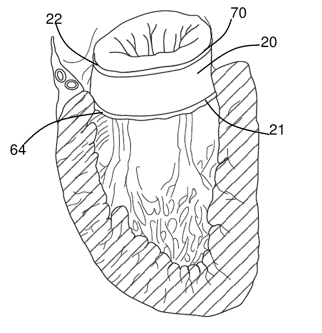
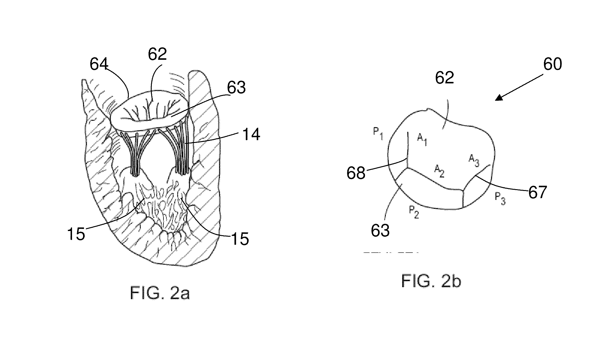
[0043]The present invention is described in greater details with reference to FIGS. 2 and 3. The mitral valve 60 comprises of two leaflets, a larger anterior leaflet 62 and smaller posterior leaflet 63, these leaflets acts like doors, opening and closing by the pressure induced by the heart. The mitral valve annulus 64 holds both the anterior leaflet 62 and posterior leaflet 63. The mitral valve annulus 64 is circumflexed around with annulus posterior 66 and anterior 65. The present device is used to repair a Mitral valve having a prolapse. This is achieved by implanting an annuloplasty tube inside the heart.

[0044]One embodiment of annuloplasty tube 20 of the present invention is illustrated in FIG. 4a. The main body of the tube 18 is substantially smooth, continuous, and generally curvilinear wit...


PUM


Abstract

A mitral valve annuloplasty tube and method for implanting the same to treat mitral valve regurgitation by establishing new mitral valve annulus. The method comprising of cutting and detaching the leaflets of a mitral valve and displacing them to a different location, preferably to an upstream location of the blood flow, in order to compensate for the height of the valve prolapse. The displacement zone being filled with the present annuloplasty tube.

Description

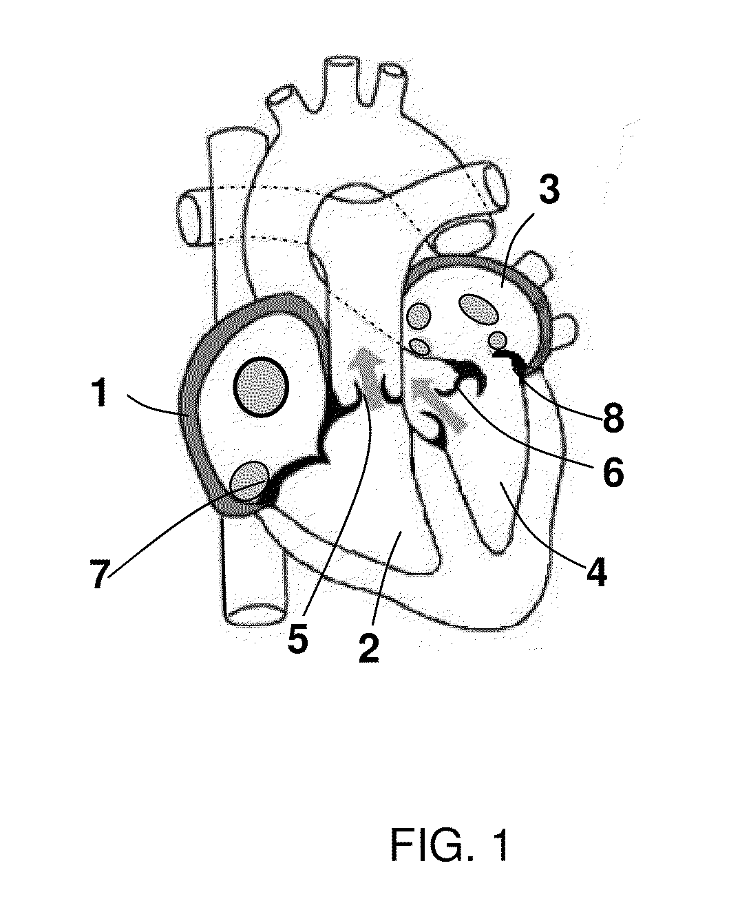
FIELD OF THE INVENTION[0001]The present invention relates to a method and apparatus for establishing a new mitral valve annulus in the place of native mitral valve using an annuloplasty tube.BACKGROUND OF THE INVENTION[0002]The present invention relates to the repairment of the mitral valve using a novel annuloplasty tube and a procedure for its implantation to treat mitral valve regurgitation, a cardiac abnormality where the mitral valve of the heart does not close properly.[0003]Heart is divided into the right and the left sides, which are separated by a septum. Heart has four chambers as illustrated in FIG. 1: right atrium 1, right ventricle 2, left atrium 3 and left ventricle 4. The blood flow in the heart is regulated by four valves, namely, pulmonary valve 5, aortic valve 6, tricuspid valve 7, and mitral valve 8. The right side of the heart pumps blood from the heart to the lungs through the pulmonary artery. The left side of the heart pumps blood to other parts of the body th...

Claims


Application Information

Patent Timeline
IPC IPC(8): A61F2/24
CPCA61F2/2445
Inventor ASHE, KASSEM
Owner ASHE KASSEM
Learn More