
Bone anchored surgical mesh

a surgical mesh and bone anchored technology, applied in the field of bone anchored surgical mesh, can solve the problems of spinal deformity, pain, neurologic problems including myelopathy or nerve root symptoms, and the subsequent spinal operation and revision surgery are much more difficult, so as to and reduce the risk of fractur

Inactive Publication Date: 2011-02-10
ONIKE TECH
View PDF16 Cites 23 Cited by
  • Summary
  • Abstract
  • Description
  • Claims
  • Application Information

AI Technical Summary

Benefits of technology

The mesh enhances spinal stability, reduces the risk of complications during revision surgeries, allows for easier application and adjustment, and maintains segmental spinal motion, thereby preventing accelerated degeneration of adjacent disc levels and improving rotational stability post-laminectomy.

Problems solved by technology

The neural elements become more vulnerable to traumatic injuries after surgery.
Furthermore, laminectomy can result in the compromise of spinal stability, leading to spinal deformity, pain, and neurologic problems including myelopathy or nerve root symptoms.
Following a laminectomy, subsequent spinal operations and revision surgeries are much more difficult than a first surgery on the spine.
Scar tissue forming over the dura is a significant problem after surgery and frequently a cause of further spinal pathology symptoms.
Because of scar tissue formation, subsequent surgeries are more difficult because of a lack of clear anatomic boundaries between the dura and other soft tissues.
It is not uncommon to injure the dura during these subsequent surgeries, thereby resulting in leakage of spinal fluids and sometimes injury to the neural elements.
Soft coverings do not provide any significant protection to the dura from penetrating trauma.
Also, these sheet-like dural coverings and soft tissue grafts frequently do not result in a clearly defined dissection plane between the dura and the other posterior soft tissues during subsequent surgery.
Decompression laminectomy, particularly in the cervical spine, can result in spinal instability, leading to spinal deformity, pain, and neurologic problems including myelopathy.
However, the anterior approaches require a spinal fusion that limits functional mobility of the cervical spine thereafter.
However, the procedure of laminoplasty can be technically challenging, because removal of the lamina en bloc is difficult, and runs the risk that the lamina will move out of place during healing, resulting in compression of the spinal cord.
However, this procedure can be dangerous because the spinal canal must be entered when passing the wire underneath the lamina.
Pressure on the spinal cord can result in quadriplegia.
Therefore, rigid posterior spinal instrumentation is usually not used in combination with an artificial disc.
Patients who have had lumbar laminectomy with removal of posterior elements, for example, the lamina, have therefore not been good candidates for total disc replacement with an artificial disc.
However, complications of extensive bone growth impinging on the neural elements was frequently reported and posterior midline fusion has been largely abandoned.
However, there is no present method or system for placing BMP in a controlled fashion, over exposed dura, after laminectomy.
Present orthopedic plating systems are not presently designed to cover over the posterior midline of the spine to protect the dura.
These devices require single points of screw fixation and do not permit sliding.
The bridges do not permit sliding.
These devices require fixed anchoring holes for receiving a fastener, and do not permit sliding.
Meshes or mats containing round fixed holes for placement of screws do not give a surgeon flexibility or leeway in screw placement.
A device with fixed spacing of single round holes may not be capable of being aligned with a patient's anatomy to provide optimal fastening to a patients bone, or simply may not fit a particular patient or spinal level at all, because the patient's anatomy may not line up with the predetermined fixed round holes.
Furthermore, fixed round holes do not permit a sliding or gliding motion upon the anchoring screws.

Method used


Image

  • Bone anchored surgical mesh
  • Bone anchored surgical mesh
  • Bone anchored surgical mesh

Examples


Embodiment Construction

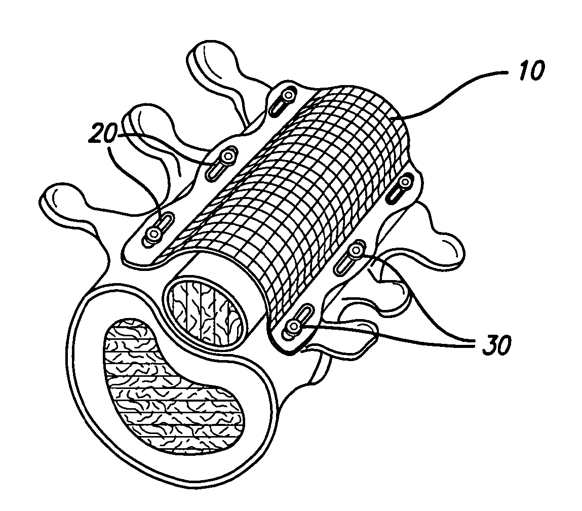
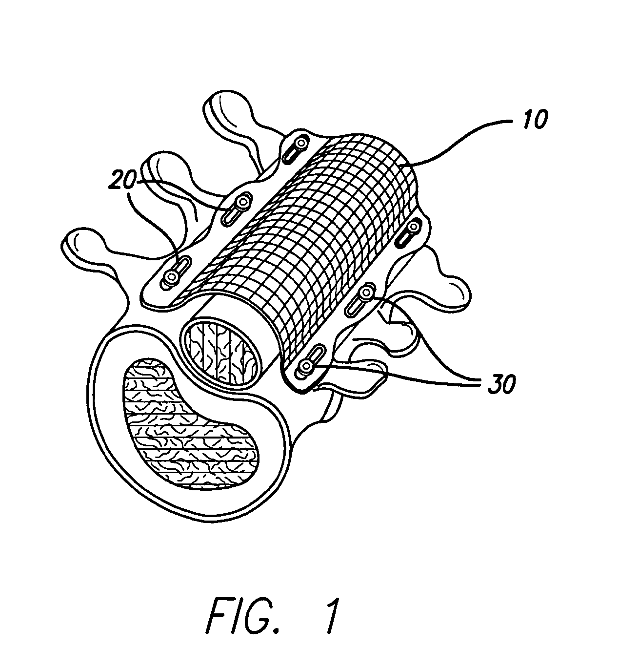
[0031]As illustrated in FIG. 1, in general terms, the present invention provides a new and improved spinal implant including a surgical mesh covering that can be anchored to bone. Although described herein for application to the spine, application to other bony anatomic structures is also included in the invention. The surgical mesh 10 has elongated slot-like anchoring members 20 which receive bone screws or other bone fasteners 30. The mesh structure may be affixed to adjacent vertebrae with the screws. The screws or other bone fasteners 30 are placed within the slot-like anchoring members 20 formed in the mesh structure which allows the mesh structure to articulate and move with respect to other mesh structures located on adjacent vertebrae. The elongated slots of the anchoring members 20 provide for variable placement of the screws 30 and are capable of permitting sliding and gliding motion of an anchoring member upon a bone fastener 30. Preferably, the anchoring member slidable ...


PUM


Abstract

A bone-anchored surgical mesh has slot-like anchoring members that allow for the variable placement of screws and other bone fasteners. This permits the surgeon discretion in the placement of bone fasteners used to attach the mesh to the patient's bone. The elongate openings of the anchoring members allow for a sliding motion between the bone fasteners and the anchoring members, and facilitates positioning and articulation of the mesh. The anchoring members may include bushings to aid the sliding motion of the anchoring member on the bone fastener. In one embodiment, the mesh consists of shorter modular strips that overlap each other such that a single bone fastener is passed through two overlapping anchoring members to lock the two modular mesh strips together. Additional modular mesh strips can be added on at either end, as desired, to provide the desired length of dural coverage.

Description

FIELD OF THE INVENTION[0001]The present invention relates generally to orthopedic devices. More specifically, the present invention relates to orthopedic devices that are fastened to bone such as surgical meshes and spinal implants useful for covering, replacing, and supporting spinal elements.BACKGROUND OF THE INVENTION[0002]Spinal surgery is a common medical procedure in the United States and throughout the world. Spinal surgery is typically performed to decompress nerves and / or to stabilize the spinal elements. Spinal surgery can involve either anterior or posterior approaches to the spine. There are variations in the spinal anatomy of the cervical, thoracic, and lumbar levels of the spine. However, there are common anatomical elements of the spine at all the levels. The anterior bone elements of the spine include the vertebral bodies, with the interposed intervertebral discs. The posterior bone elements of the spine include the lamina, the spinous processes, the facet joints, th...

Claims


Application Information

Patent Timeline
Patent Type & Authority Applications(United States)
IPC IPC(8): A61F2/44A61B17/00
CPCA61B17/70A61F2/0063A61B17/8085A61B17/7071
Inventor WILLIAMS, LYTTON A.
Owner ONIKE TECH
Learn More