Floating disk for separating blood components

a floating disk and blood component technology, applied in separation processes, laboratory glassware, centrifuges, etc., can solve the problems of significant affecting the recovery rate, difficult to determine the density of the red blood cell layer that develops during centrifugation with precision, and differences in the recovery rate as much as fifty percent, so as to minimize the difference, minimize the vertical difference, and minimize the amount of other cells

Active Publication Date: 2011-02-17
GLOBUS MEDICAL INC
View PDF1 Cites 50 Cited by
  • Summary
  • Abstract
  • Description
  • Claims
  • Application Information

AI Technical Summary

Benefits of technology

In accordance with another feature of the invention, the thickness of the positioning part is made to be small such that it minimizes the difference between its vertical positions with respect to the interface for the maximum and minimum expected densities of the plasma and red blood cell layers. This latter feature utilizes the phenomenon that for an element floating between two fluid layers the relative proportion of the floating element in one layer and in the other layer is determined by the relative densities of the layers. Configuring the separating element to include a positioning part and a separating part where the majority of the mass is in a thin positioning part minimizes the vertical difference between the locations of the separating part from the interface. This allows the layer of interest to be transferred, as by decanting, while minimizing the amount of other cells, such as red blood cells also transferred.

Problems solved by technology

Analysis of the fluid dynamics of centrifugal separation of the components of physiological fluids such as blood has shown that the density of the red blood cell layer that develops during centrifugation is difficult to determine with precision due to the factors discussed above affecting the sedimentation rate of the red blood cells.
Because the layer of the desired cells, such as platelets and bone marrow stem cells, after centrifugal separation is generally very thin, an error in the position of the separating element may affect the recovery rate significantly.
That is, an error in the placement of the separating element on the order of the thickness of the layer of desired cells could result in differences in the recovery rate by as much as fifty percent.

Method used


Image

  • Floating disk for separating blood components
  • Floating disk for separating blood components
  • Floating disk for separating blood components

Examples


Embodiment Construction

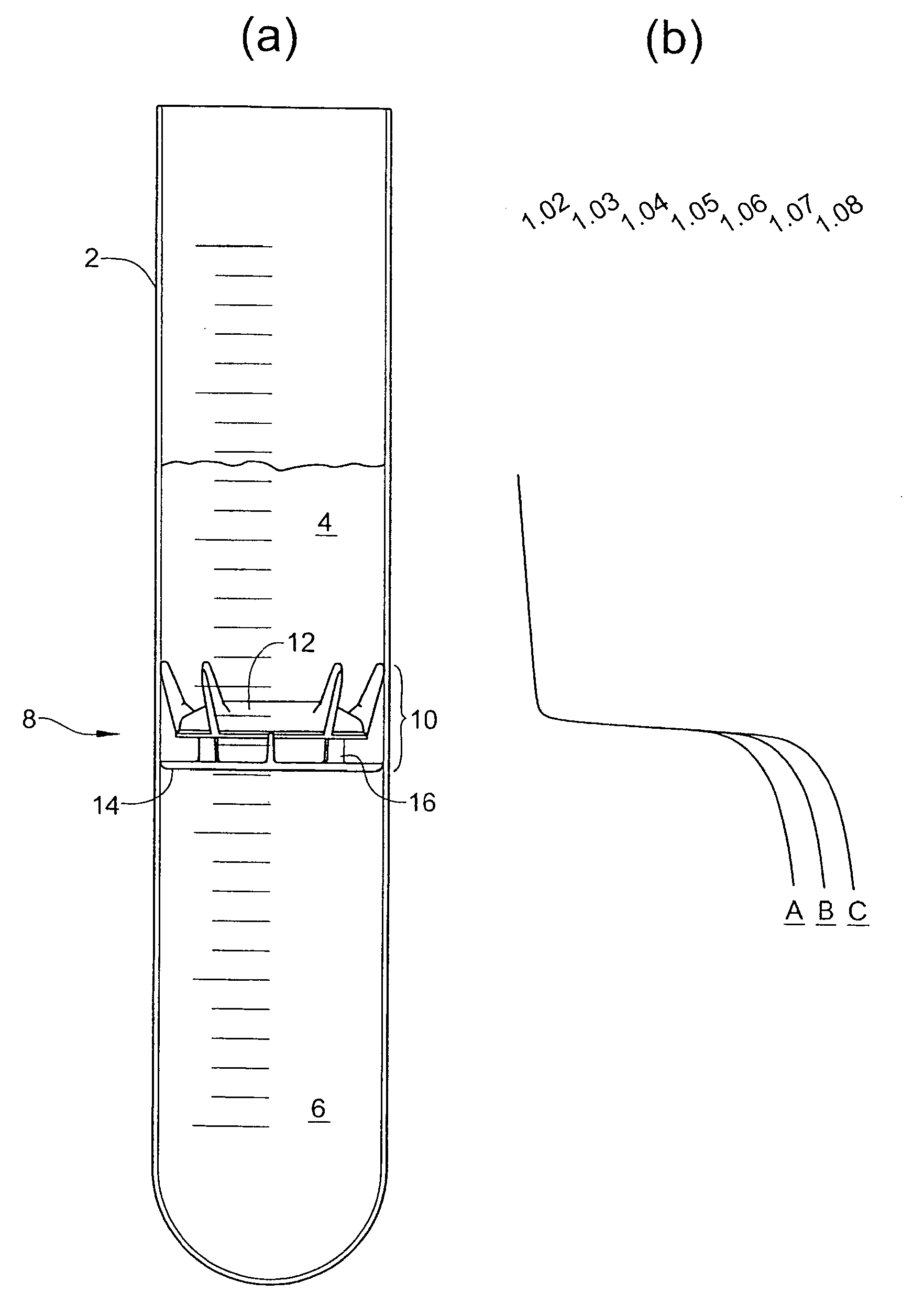
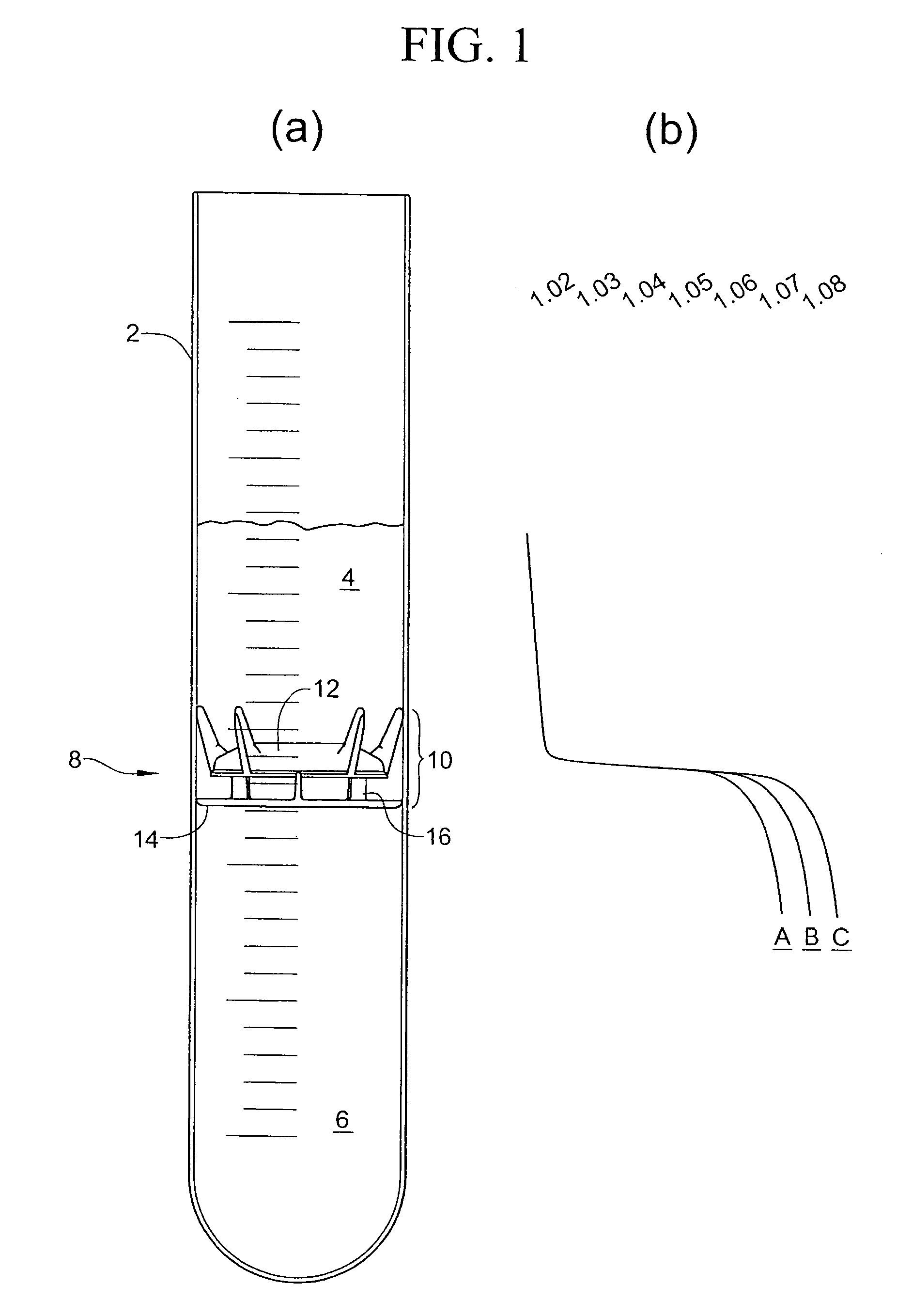
With reference to figure la, a processing tube 2 has a physiological fluid therein. The processing tube 2 is illustrated as a simple cylindrical tube, but it will be appreciated that it can take any of various shapes. In a preferred embodiment, the processing tube 2 is one chamber of a two-chamber processing disposable such as that shown in U.S. Pat. No. 6,398,972. Alternatively, the processing tube 2 is part of a syringe arranged to express the separated components through one end of the syringe or to separate the supernatant in other ways. The processing tube is typically cylindrical whereby a circular floating disk of fixed diameter is freely movable in the tube to assume a location at the interface between components to be separated. Other configurations utilizing the principles of the invention are possible.

The physiological fluid in the processing tube 2 of FIG. 1a is shown after it has been subjected to centrifugation to separate the several components according to their dens...


PUM

PropertyMeasurementUnit
massaaaaaaaaaa
total massaaaaaaaaaa
stabilityaaaaaaaaaa

Abstract

A floating separating element for use in centrifugal separation of components of a physiological fluid comprises a positioning part and a separating part, where the positioning part is designed to automatically assume a position in a supernatant and a separating part is positioned at a desired location with respect to the interface between the supernatant and heavier components. In preferred embodiments the physiological fluids are blood or bone marrow aspirate, and the heavier components comprise red blood cells. The positioning part comprises the majority of the mass of the separating element and is thin so that differences in the position of the separating element with respect to the interface are small compared to differences in the densities of the separated compoments, particularly the component comprising red blood cells. A method allows red blood cells to move the separating element during decanting to ensure complete decant of the supernatant.

Description

TECHNICAL FIELDThis invention relates to the art of fractionation of physiological fluids. In particular, the invention relates to the art of fractionation of blood and bone marrow aspirate by centrifugation.BACKGROUNDBlood is commonly separated into its components by centrifugation. This may be done for many reasons, one of which is to obtain a selected component for use in treating a patient. For example, as disclosed in U.S. Pat. No. 6,398,972 (Blasetti) blood is separated into components by centrifugation to obtain platelet rich plasma, which is used in the autologous treatment of a patient. In this system, the whole blood is placed in one chamber of a processing unit, and the platelets and plasma are decanted to a second chamber after a first centrifugal spin. Then, subjecting the processing unit to a second centrifugal spin separates the platelets from the plasma. It is important to ensure that the platelets, as well as other desired components, such as white blood cells, are ...

Claims


Application Information

Patent Timeline
Patent Type & Authority Applications(United States)
IPC IPC(8): B01D21/26
CPCA61M1/029A61M1/3693B01D21/26G01N33/491B01L3/50215Y10T436/25375B04B7/08B01L2200/025B01L2300/044B01L2300/0861B01L2400/0409B01D21/262
Inventor ELLSWORTH, JAMES R.
Owner GLOBUS MEDICAL INC
Why Eureka
Try Eureka