Method for creating, trapping and manipulating a gas bubble in liquid

a gas bubble and liquid technology, applied in the field of optical trapping, can solve the problems of gas bubble generation and emission from the focal point area, the limitation of known optical tweezers, and the inability to trap gas bubbles in liquid

Inactive Publication Date: 2011-02-17
CARL ZEISS SMS GMBH
View PDF23 Cites 13 Cited by
  • Summary
  • Abstract
  • Description
  • Claims
  • Application Information

AI Technical Summary

Benefits of technology

[0034]Furthermore, in accordance with some embodiments of the present invention, the method includes using a controller to control the moving of the focal zone within the liquid.

Problems solved by technology

Some limitations of known optical tweezers include:
It is known that focusing of laser pulses inside a liquid causes the generation and emission of gas bubbles from the area of the focal point, due to non-linear absorption and breakdown plasma formation.
However this method does not allow for trapping a gas bubble in the liquid.
However it is impossible using this method to make a stable trap for a gas bubble localized in a predetermined point in the liquid using a self-focusing laser beam, and this may be because of the non-controllability of the self-focusing process.
The size of the trapped gas bubble is uncontrollable too and can not be changed.
The use of high average laser power above 210 mW and white light generation may cause damage of surrounding objects which significantly imparts limitations on many applications, for instance, in medicine and biology.

Method used


Image

  • Method for creating, trapping and manipulating a gas bubble in liquid
  • Method for creating, trapping and manipulating a gas bubble in liquid
  • Method for creating, trapping and manipulating a gas bubble in liquid

Examples


example 1

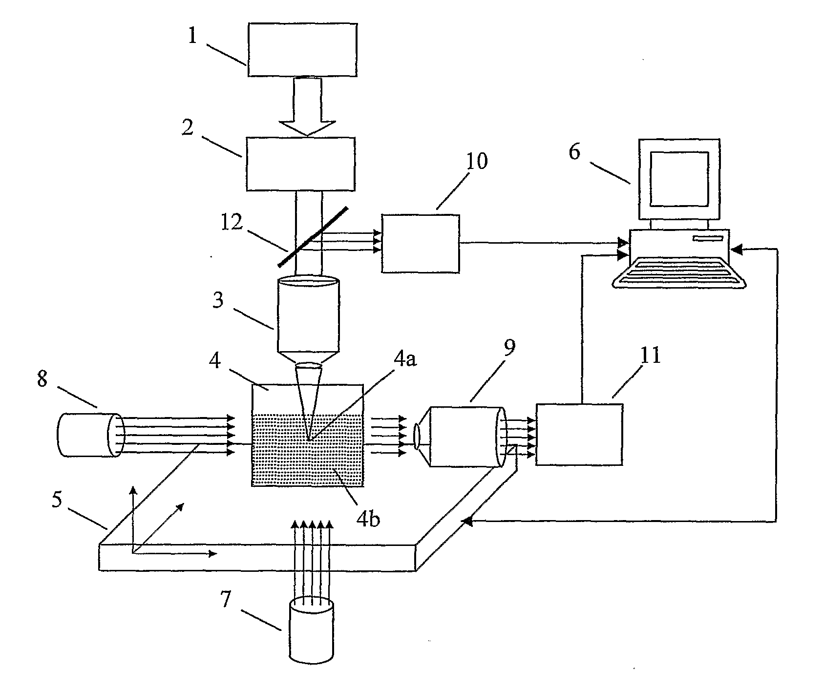
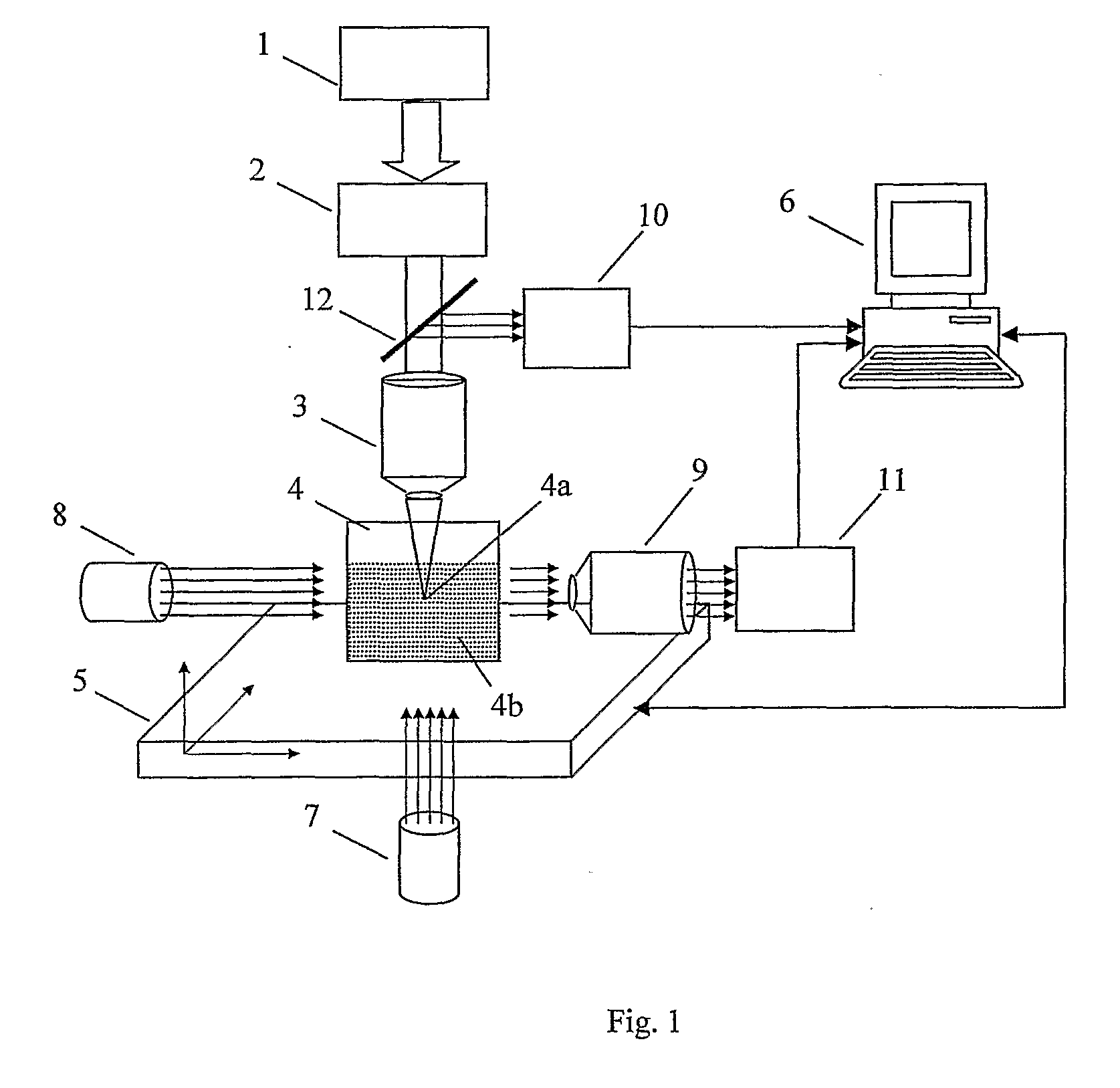
[0056]Laser pulses of 200 fs width and wavelength of 800 nm (1, FIG. 1) were directed through a variable attenuator (2) and were focused in distilled water by an dry objective (3) with a numerical aperture 0.55. A cuvette (4) with water (4b) was moved relative to the focal point (4a) of the objective with the help of a three-axis open frame positioning system (5), controlled by a computer (6). The setup had two vision systems working along and perpendicular to the direction of laser beam. Each vision system had an illumination source (7, 8), an objective (3, 9) and a CCD camera (10, 11). Observation along the laser beam was performed through the same objective (NA=0.55, compensation depth 6.3 mm), as the initiating breakdown laser radiation using a dichroic mirror (12). In the vision system perpendicular to the laser beam the objective (9) with NA=0.3 was used.

[0057]As it was mentioned above, typically initiation of breakdown in water by high repetition pulses is followed by residua...

example 2

[0059]200 fs laser pulses of Ti-Sapphire laser with pulse energy of 150 nJ and 100 kHz repetition rate were focused in the water by water immersion 0.75 NA objective. In this case a stable trapped bubble was observed at any depth of the focal point of the objective in water. A trapped bubble can be moved in water either by changing the angle of laser beam incidence on the focusing objective or by moving the focal point relative to the water container both along the beam axis and in the lateral direction.

example 3

[0060]50 fs laser pulses of Ti-Sapphire oscillator with pulse energy of 100 nJ and 5 MHz repetition rate were focused in the water by water immersion 0.75 NA objective. In this case a stable trapped bubble was observed at any depth of the focal point of the objective in water. A trapped bubble can be moved in water either by changing the angle of laser beam incidence on the focusing objective or by moving the focal point relative to the water container both along the beam axis and in the lateral direction.

[0061]Experiments showed that the trapped bubble diameter practically does not change in the time interval between consecutive laser pulses (10 μs), i.e. it does not undergo cavitation oscillations.

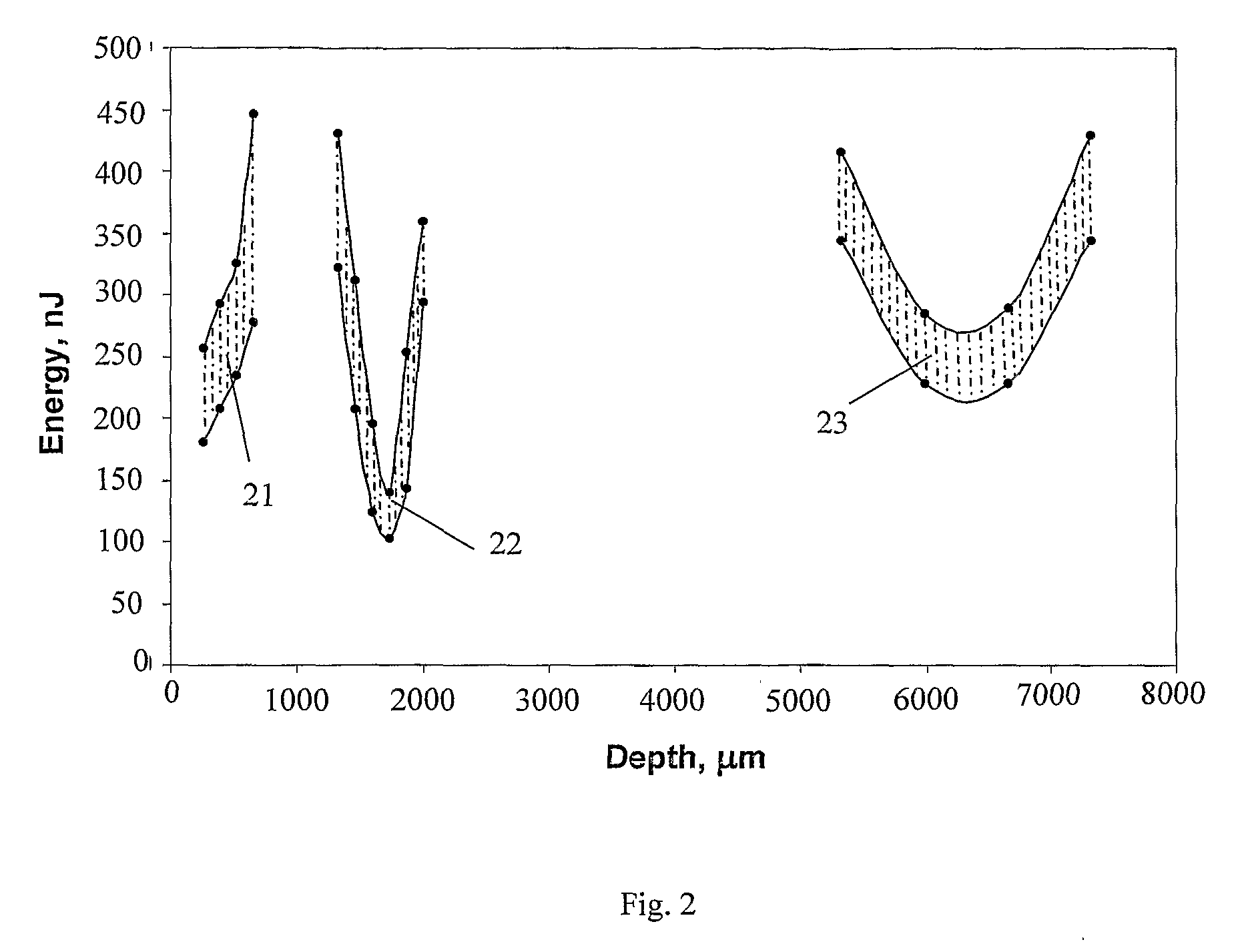
[0062]It was experimentally found out that gas bubble trapping mode occurs only when the objective focal point is moved in water at some optimal depth, for which the spherical aberration of the used objective is minimal. This is illustrated in FIG. 2, showing the diagram of the region of...


PUM


Abstract

A method for producing, trapping and manipulating a gas microbubble in liquid is disclosed. The method includes providing a pulsed laser source for generating a pulsed laser radiation and focusing optics; and focusing a pulsed laser radiation to a focal zone within the liquid, with energy exceeding the threshold of optical breakdown in the liquid at the focal zone. It is also suggested to use focusing optics to focus the laser beam to a focal point at a depth close to the compensation depth of the focusing optics for spherical aberration.

Description

FIELD OF THE INVENTION[0001]The present invention relates to optical trapping. More particularly the present invention relates to a method for creating, trapping and manipulating a gas bubble in liquid.BACKGROUND OF THE INVENTION[0002]Trapping and manipulating microparticles have great importance in nanotechnology and microtechnology, as well as in medical and biological applications. Trapping and manipulating particles usually involve the use of optical traps (optical or laser tweezers) imparting light pressure on a microparticle in a liquid. Despite the small force of optical tweezers in some cases it is sufficient for non-contact trapping and manipulation of cells and other microparticles.[0003]A demonstration of the feasibility of microparticles non-damaging trapping and moving using optical tweezers was given in the paper of A. Ashkin “Acceleration and trapping of particles by radiation pressure”, Phys. Rev. Lett. 24(4), 156-159 (1970). Since that time the design of optical twe...

Claims


Application Information

Patent Timeline
Patent Type & Authority Applications(United States)
IPC IPC(8): G21K5/00
CPCG02B21/32A61B18/26A61B2018/263
Inventor OSHEMKOV, SERGEYDVORKIN, LEVDMITRIEV, VLADIMIR
Owner CARL ZEISS SMS GMBH
Why Eureka
Try Eureka