
Light emitting device, display device, and color conversion sheet

a technology of display device and light-emitting device, which is applied in the direction of non-linear optics, lighting and heating apparatus, instruments, etc., can solve the problems of affecting the quality of light-emitting device, etc., to achieve favorable handling and suppress the effect of color-converting layer deterioration

Active Publication Date: 2011-02-17
SATURN LICENSING LLC
View PDF8 Cites 73 Cited by
  • Summary
  • Abstract
  • Description
  • Claims
  • Application Information

AI Technical Summary

Benefits of technology

[0013]In view of the foregoing, it is an object of the present invention to provide a color conversion sheet capable of suppressing deterioration of a color conversion layer which converts one color light into another color light, and realizing favorable handling, and a light emitting device using the light conversion sheet, and a display device.
[0017]In the light emitting device and the color conversion sheet, and the display device of the present invention, the part of the color light emitted from the light source section is converted into another color light by the color conversion layer, and surface emission is performed by color mixture of one and the other color light. By sealing such a color conversion layer by the impermeable sealing sheet, water is prevented from entering the color conversion layer.
[0018]According to the light emitting device and the color conversion sheet of the present invention, since the color conversion layer converting the part of the color light emitted from the light source section into another color light is sealed by the impermeable sealing sheet, it is possible to suppress deterioration of the color conversion layer. Also, it is possible to realize favorable handling in comparison with the case where the color conversion layer is sealed by a glass substrate.

Problems solved by technology

However, in the method of the Patent literature 3, since it is necessary to further adjust the internal atmosphere by applying the phosphor layer inside the outer cap, the manufacturing process is complicated.
Also, application non-uniformity of the phosphor layer is likely to be generated, and there is a risk that the chromaticity is varied.
However, the handling is poor in the heavy glass substrate, and it is difficult to cope with a large and thin display in particular.

Method used


Image

  • Light emitting device, display device, and color conversion sheet
  • Light emitting device, display device, and color conversion sheet
  • Light emitting device, display device, and color conversion sheet

Examples


application examples

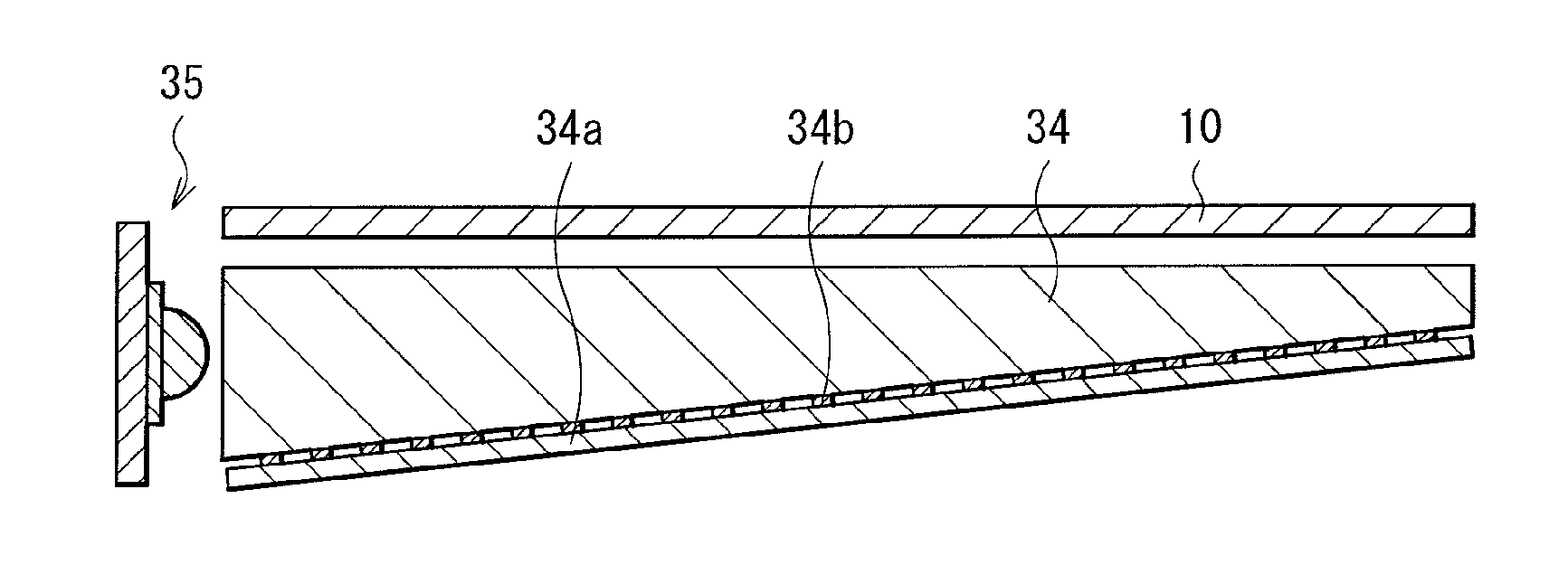
[0059]The phosphor sheet 10 as described above is, for example, applicable to a display device 1 (a light emitting device 3) as illustrated in FIG. 5.

[0060]The display device 1 includes the light emitting device 3 as a backlight composed of a light source section 2 and the phosphor sheet 10, and a display panel 4 driven based on image data. Between the light emitting device 3 and the display panel 4, various optical function films such as a diffusion plate 5, a diffusion film 6, a lens film (light condensing member) 7, and a reflective polarizing film 8 are sequentially arranged from the light emitting device 3 side.

[0061]The light source section 2 in which a plurality of blue LEDs 21 are arranged on a substrate 20 performs surface emission as a whole. The phosphor sheet 10 is arranged immediately above such a light source section 2.

[0062]In the display panel 4, for example, a liquid crystal layer is sealed between a TFT substrate in which a pixel electrode, a TFT (Thin Film Transis...


PUM


Abstract

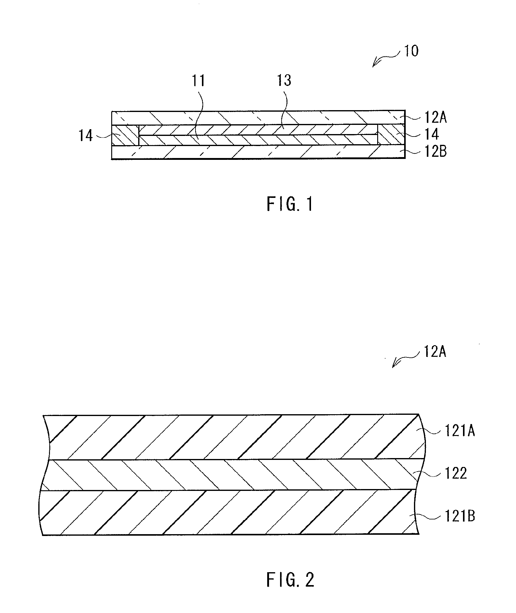
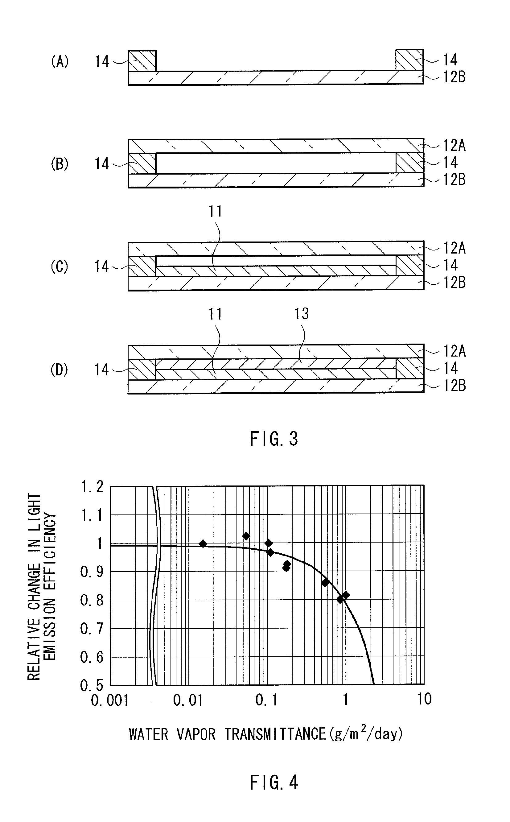
There is provided is a display device capable of suppressing deterioration of the color conversion layer which converts one color light into another color light, and realizing favorable handling and a display device using the color conversion layer, and a color conversion sheet. A phosphor sheet 10 is, for example, arranged immediately above a light source such as a blue light emitting diode, and obtained by sealing a phosphor layer 11, which converts a part of blue light into another color light, by sealing sheets 12A and 12B. The sealing sheets 12A and 12B are bonded with the phosphor layer 11 in between by a first bonding layer 13 and a second bonding layer 14. Since the phosphor layer 11 is sealed by the sealing sheets 12A and 12B including a water vapor barrier layer 122 held between resin sheets 121A and 121B, water vapor is prevented from entering into the phosphor layer, and a chemical reaction is less likely to be generated between the phosphor layer 11 and the water vapor barrier layer 122.

Description

TECHNICAL FIELD[0001]The present invention relates to a light emitting device, for example, including a light source, and a color conversion layer which converts a color of light from the light source, a display device using the light emitting device, and a color conversion sheet.BACKGROUND ART[0002]From the past, a liquid crystal display (LCD; Liquid Crystal Display) has been used as a thin display device. A backlight irradiating the whole surface of a liquid crystal panel from behind is utilized in the liquid crystal display, and the liquid crystal display is roughly classified into the direct method and the edge light method, depending on the structure thereof. In the edge light system, surface emission is performed on the top face of a light guide plate by allowing light to enter from the side face of the light guide plate, and propagate inside the light guide plate. Also, in the direct system, the surface emission is performed by arranging a plurality of fluorescent lamps in pa...

Claims


Application Information

Patent Timeline
IPC IPC(8): G02F1/1335F21V9/00F21V11/00F21V7/22F21V9/16F21S2/00F21V31/00F21Y101/02G02F1/13357H01L33/00H01L33/32H01L33/50
CPCG02B6/0023G02B6/0038G02B6/0043G02F2001/133614G02B6/005G02B6/0073G02F1/133603G02B6/0046G02F1/133614
Inventor TSUKAHARA, TSUBASAITO, YASUSHINADA, NAOJIOSHIMA, YOSHIROCHUBACHI, HIDEYA
Owner SATURN LICENSING LLC
Learn More