Oral-esophageal-gastric device to diagnose reflux and/or emesis

a gastric device and reflux technology, applied in the field of medical devices and testing, can solve the problems of many patients' inability to address this issue, and many older women's loss of extrinsic suppor

a gastric device and reflux technology, applied in the field of medical devices and testing, can solve the problems of many patients' inability to address this issue, and many older women's loss of extrinsic suppor

US20110040211A1Active Publication Date: 2011-02-17PNEUMOFLEX SYST

Image

  • Oral-esophageal-gastric device to diagnose reflux and/or emesis
  • Oral-esophageal-gastric device to diagnose reflux and/or emesis
  • Oral-esophageal-gastric device to diagnose reflux and/or emesis

Examples


Embodiment Construction

[0059]The present invention will now be described more fully hereinafter with reference to the accompanying drawings, in which preferred embodiments of the invention are shown. This invention may, however, be embodied in many different forms and should not be construed as limited to the embodiments set forth herein. Rather, these embodiments are provided so that this disclosure will be thorough and complete, and will fully convey the scope of the invention to those skilled in the art. Like numbers refer to like elements throughout.

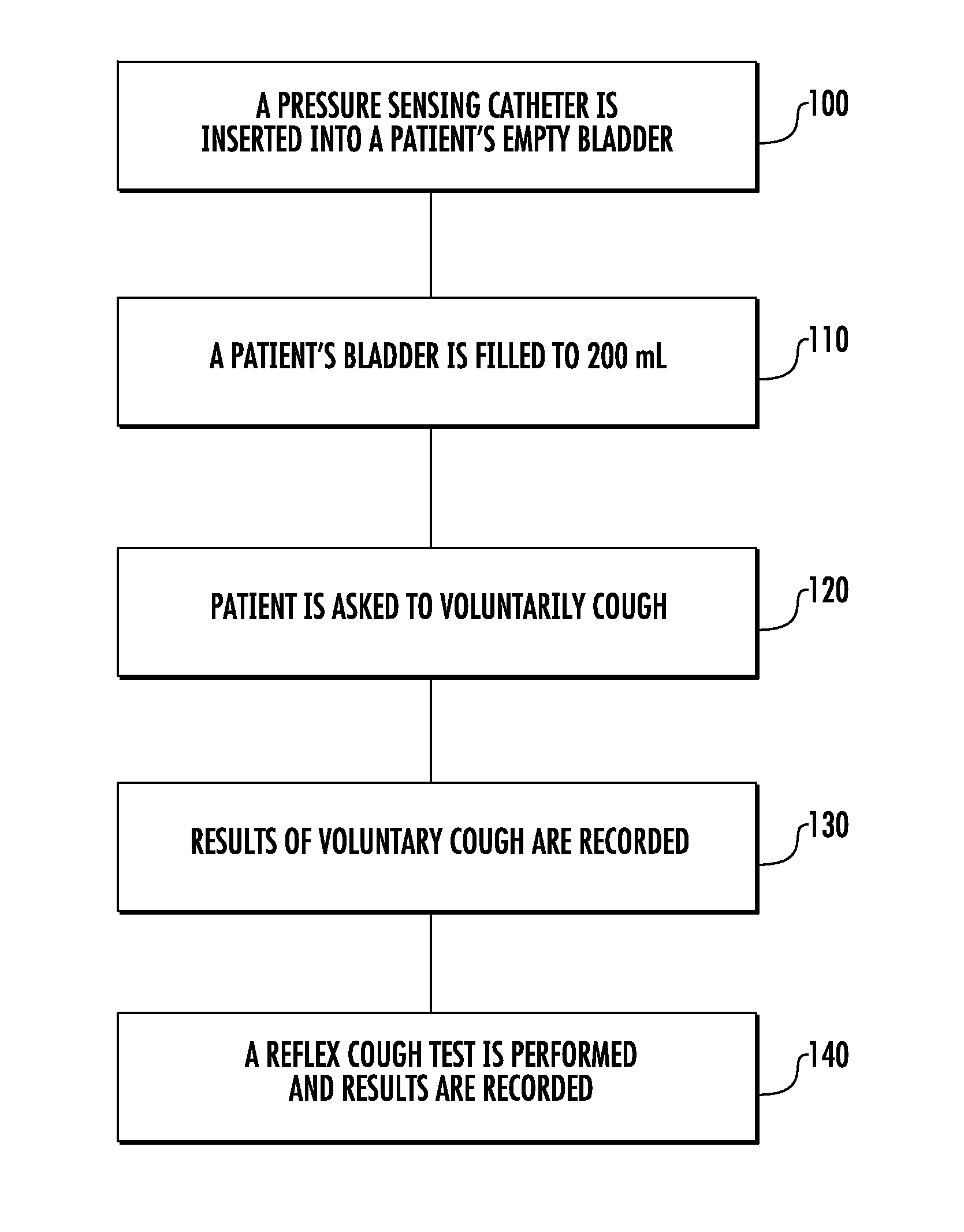
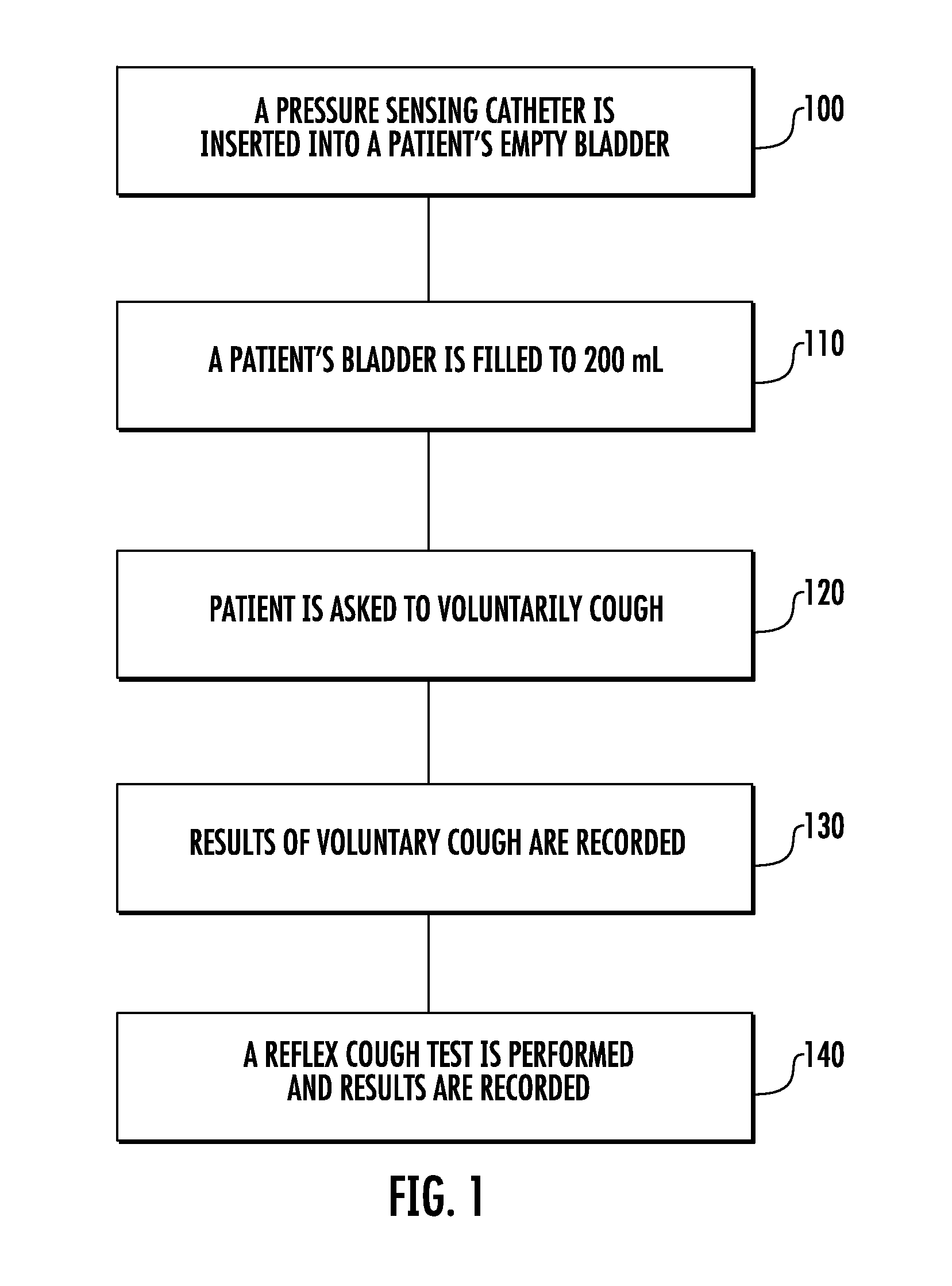
[0060]FIG. 1 shows a flowchart of a technique for evaluating a patient for urinary stress incontinence in accordance with one aspect of the invention. As an initial step, pressure sensing catheter is inserted into a patient's empty bladder (100). The patient's bladder is then filled slowly with sterile water until 200 ml have been delivered (110).

[0061]The patient is then asked to voluntarily cough (120) and the results of the voluntary cough are recorded ...


PUM


Abstract

A system and method diagnoses esophageal reflux in a patient. A catheter includes a first pressure sensor configured to measure intra-abdominal pressure when the catheter is inserted into the stomach of a patient. A second pressure sensor is located proximal to the distal tip and configured to measure intra-thoracic pressure. A pH indicator is carried by the catheter body and configured to indicate that reflux has occurred in response to an involuntary reflex cough test. A processing device is configured to receive data regarding the first and second pressure sensors and regarding the pH indicator and process that data and assess if reflux is present during the involuntary epoch.

Description

RELATED APPLICATION(S)[0001]This application claims priority to U.S. provisional application Ser. Nos. 61 / 296,304, filed Jan. 19, 2010; 61 / 311,882, filed Mar. 9, 2010; and 61 / 356,895, filed Jun. 21, 2010, and is a continuation-in-part of U.S. patent application Ser. No. 12 / 643,251 filed Dec. 21, 2009, which claims priority to prior filed U.S. provisional application Ser. No. 61 / 139,649 filed Dec. 22, 2008, and prior filed U.S. provisional application Ser. No. 61 / 244,167 filed Sep. 21, 2009, and which is a continuation-in-part application of prior filed U.S. application Ser. No. 11 / 550,125 filed Oct. 17, 2006, which claims priority to U.S. provisional application Ser. No. 60 / 727,740 filed Oct. 18, 2005, U.S. provisional application Ser. No. 60 / 752,351 filed Dec. 21, 2005, all disclosures which are hereby incorporated herein by reference in their entirety.FIELD OF THE INVENTION[0002]This invention is directed to the field of medical devices and testing and, more particularly, to appar...

Claims


Application Information

Patent Timeline
17 Feb 2011
Publication
US20110040211A1
IPC
A61B5/00; A61B5/103; G16H20/40; G16H50/20
CPC
A61B5/04882; A61B5/14539; A61B5/202; A61B5/205; A61B5/4211; G06F19/34; A61B5/4884; A61B5/7475
Inventors
ADDINGTON, W. ROBERT; MILLER, STUART P.