Temporary ostomy appliance

a technology of ostomy and ostomy, which is applied in the field of temporary ostomy equipment, can solve the problems of high morbidity and mortality, high cost of two such serious operations, and the inability to use temporary ileostomy as extensively, and achieves the effect of minimizing the pressure on the inside of the balloon and minimizing the potential harmful pressure on mucosal tissu

Active Publication Date: 2011-02-17
CONVATEC TECH INC
View PDF24 Cites 50 Cited by
  • Summary
  • Abstract
  • Description
  • Claims
  • Application Information

AI Technical Summary

Benefits of technology

[0008]An advantage of such balloon construction is that it generally enables lower inflation pressures to be used inside the balloon, because it is not necessary to overcome the elastic return forces in elastic material that would generally act against inflation. Also, the forces applied to the surrounding body tissue are generally more predictable and controllable, as this is equal to the inflation pressure. Minimizing the pressure on the inside of the balloon minimizes potential harmful pressure on mucosal tissue.

Problems solved by technology

However, the combination of two serious surgeries has a high morbidity and mortality problem, and the costs of two such serious operations are very high.
The risks and costs mean that a temporary ileostomy is not used as extensively as it might be in all cases.
Also, the risks of the second serious operation may be too high for many patients resulting in the temporary becoming a permanent ostomy.

Method used


Image

  • Temporary ostomy appliance
  • Temporary ostomy appliance
  • Temporary ostomy appliance

Examples


first embodiment

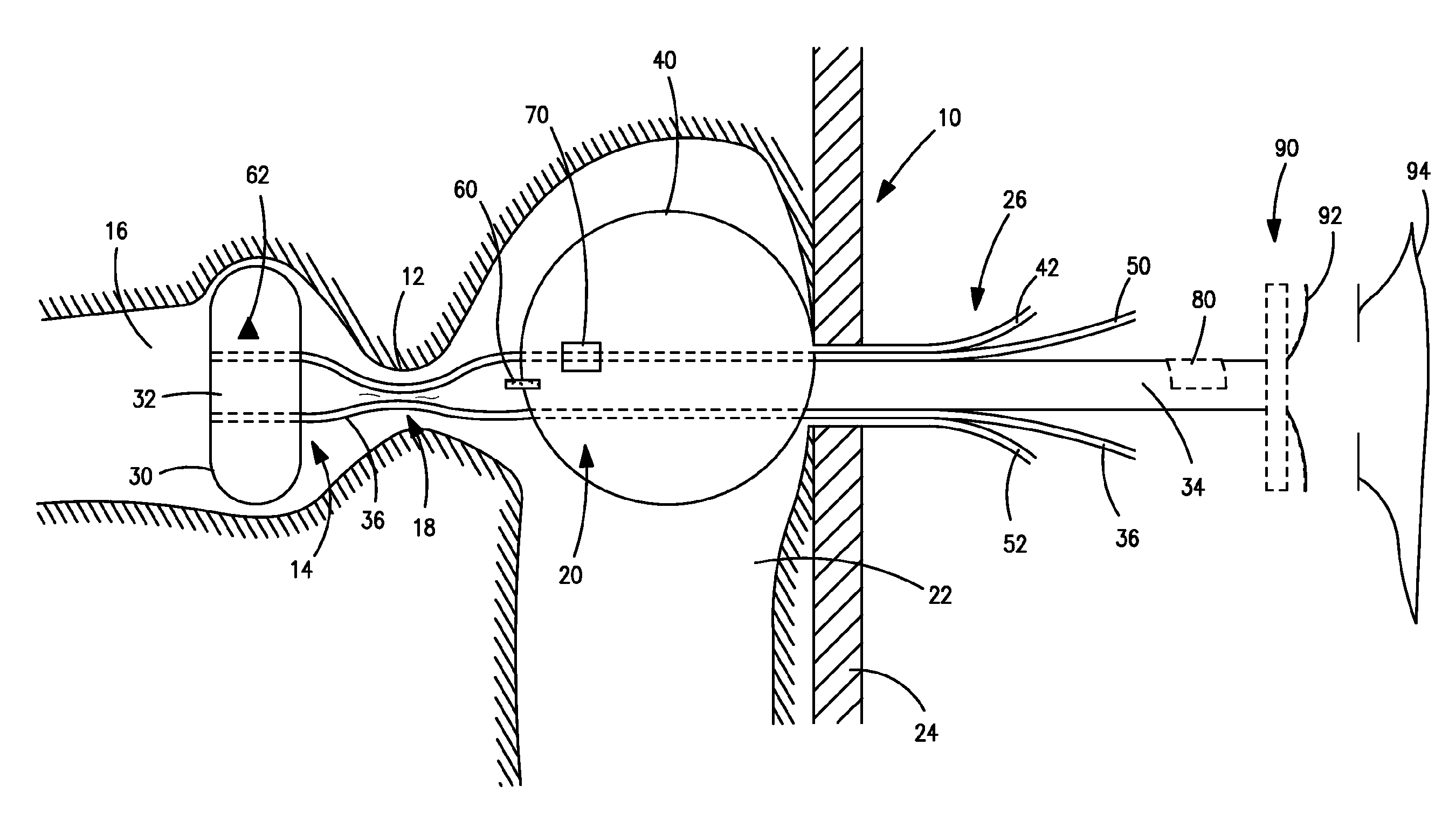
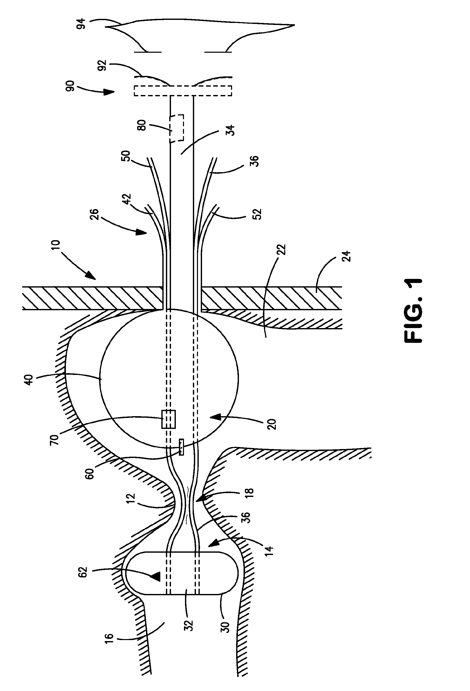
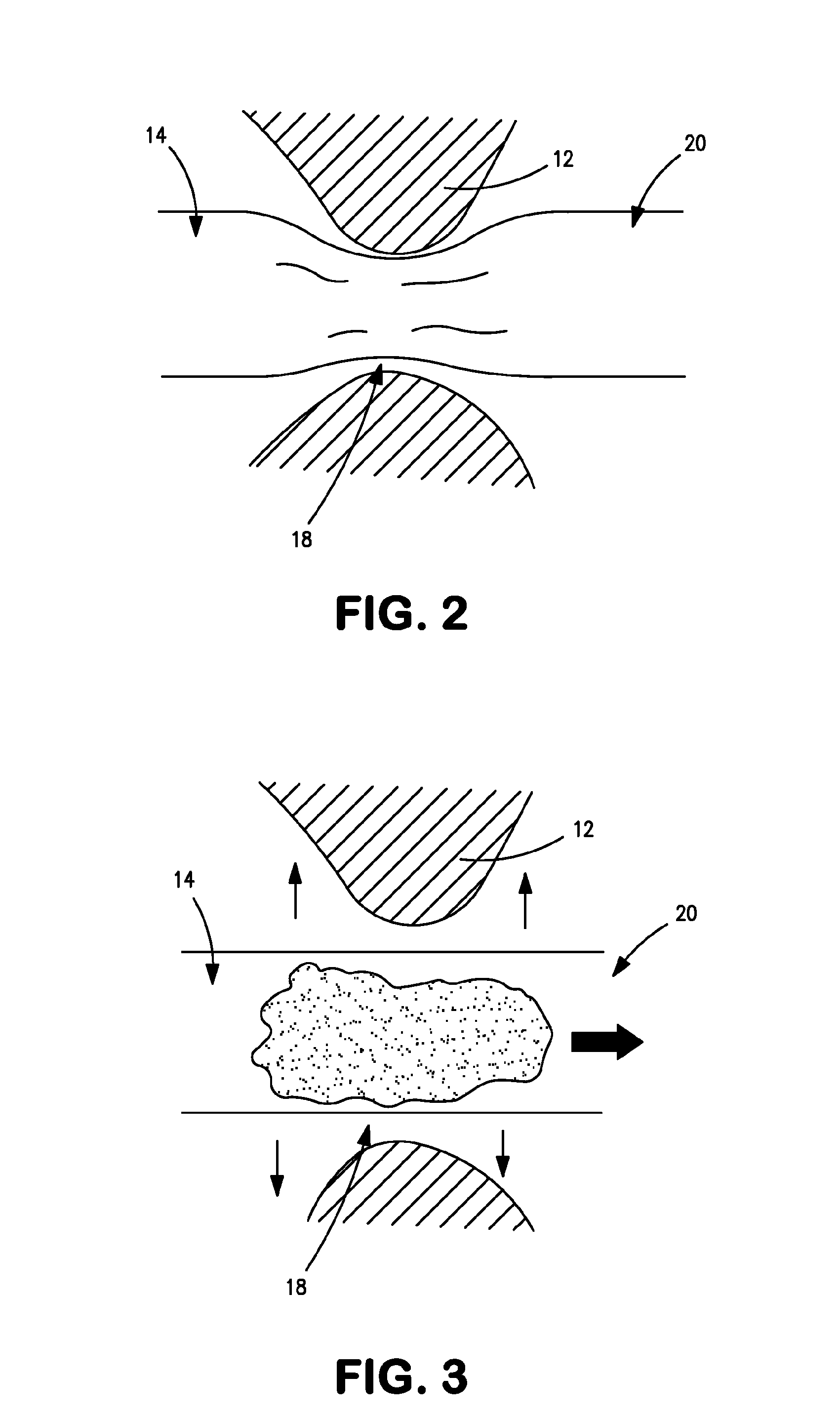
[0021]Referring to FIG. 1, temporary ostomy appliance is a transcecal ileostomy appliance comprising a catheter 10 intended for insertion through the cecal valve 12 of the intestine. The catheter 10 includes a first distal portion 14 intended to be received in the ileum 16, a second portion 18 intended to sit at the cecal valve 12, a third portion 20 intended to be received in the large intestine 22, a fourth portion 25 intended to pass through the abdominal wall 24, and a fifth proximal portion 26 intended to extend outside the body. The catheter 10 is made of any suitable material including, for example, silicone and / or polyurethane.

[0022]An inflatable blocking balloon or cuff 30 is optionally provided at the first distal portion 14 for obstructing the ileum 16, and causing effluent to be diverted through an aperture 32 into a drainage lumen 34 of the catheter 10. A blocking balloon inflation lumen 36 communicates with the blocking balloon 30 for inflation and deflation of the blo...

second embodiment

[0043]The balloon 40 may be supplemented by the removable bridge features 102 of the second embodiment, and this removable fastening may render the transcecal portion 110 of the catheter 10 unnecessary if the balloon 40 is sufficiently anchored, by the removable bridge features 102 or other means, against unwanted turning in the large intestine 22. If the transcecal portion 110 is implemented, the transcecal portion 110 may also include one or more removable bridge features 102. Such a releasable fastening may supplement the balloon 30, or the balloon 30 may be omitted from the transcecal portion 110.

third embodiment

[0044]The temporary ostomy appliance of the third embodiment may be removed without surgery in a similar manner to the first (and / or second) embodiment. The fixation balloon 40 is deflated, and the blocking balloon 30 (if implemented) is also deflated. This allows easy withdrawal of the catheter 10 without additional surgery.

[0045]Referring to FIG. 8, a fourth embodiment of temporary ostomy appliance is illustrated. The fourth embodiment may be used independently, or it may be combined with any of the features of any of the preceding embodiments. Whereas in the first-third embodiments, the appliance generally draws the large intestine 22 directly up against the abdominal wall 24 at the site where the catheter 10 passes through the abdominal wall 24 and / or enters the large intestine 22, in the present embodiment, a fender 150 is provided to separate and / or cushion the outside surface of the wall 154 of the large intestine 22 from direct contact with the abdominal wall 24. The fender ...


PUM


Abstract

A temporary ostomy appliance is disclosed, including a catheter for extending through the abdominal wall into the intestine. The catheter may be a transcecal catheter for extending through the cecal valve into the ileum. A portion of a catheter that extends through the cecal valve is made collapsible when the catheter is empty. The collapsed portion expands to permit passage of effluent. A balloon carried on the catheter is preformed with a shape and size in order to permit inflation without elastic stretching of the balloon wall material. A filament is provided for permitting a portion of the catheter to be fastened to internal body tissue by surgical sutures or staples. In order to release the fastening without further surgery, the filament is withdrawn by pulling on a proximal portion outside the body.

Description

FIELD OF THE INVENTION[0001]The present invention relates to a temporary ostomy appliance including a catheter for extending through the abdominal wall into the intestine. The invention is especially, although not exclusively, directed to a transcecal appliance that extends through the abdominal wall into the large intestine, and through the cecal valve into the ileum.BACKGROUND TO THE INVENTION[0002]There are many occasions where a temporary ileostomy would be desirable to drain effluent from the small intestine for a temporary period of time, to enable analysis, repair and / or healing at a downstream site in the large intestine. Typically, a temporary ileostomy involves two surgical operations, namely (i) a colon resection during which the abdominal wall and intestinal wall are opened to create the temporary ileostomy diversion, and (ii) a later closure operation (laparotomy) which closes the openings in the intestinal wall and the abdominal wall to restore the normal intestinal ro...

Claims


Application Information

Patent Timeline
Patent Type & Authority Applications(United States)
IPC IPC(8): A61M5/00A61M29/00
CPCA61F5/445
Inventor GREGORY, CHRISTOPHER
Owner CONVATEC TECH INC
Why Eureka
Try Eureka