Method of controlling fuel in an exhaust treatment system implementing temporary engine control

a technology of exhaust treatment system and fuel control, which is applied in the direction of electric control of exhaust treatment, machines/engines, mechanical equipment, etc., can solve the problems of reducing the functionality of the filter and subsequent engine performance, affecting both methods may affect or be affected by the amount of oxygen entering and leaving the engine, so as to facilitate the regeneration of the filter

Inactive Publication Date: 2011-02-24
CATERPILLAR INC
View PDF17 Cites 29 Cited by
  • Summary
  • Abstract
  • Description
  • Claims
  • Application Information

AI Technical Summary

Benefits of technology

[0011]In yet another aspect, the present disclosure is directed to an engine system having an engine configured to combust a fuel and air mixture to generate power and a flow of exhaust. The engine system may also have a charged air induction circuit configured to introduce compressed air into the engine. The system may also have an exhaust circuit configured to direct the flow of exhaust from the engine to the atmosphere. Further, the system may have a filter located downstream of the engine to remove particulate matter from the flow of exhaust. The system may also include a regeneration device located proximal the filter to raise a temperature of the removed particulate matter above an ignition threshold. A first valve may be located upstream of the engine to vary an amount of oxygen in the flow of exhaust. A second valve may also be located downstream of the engine and upstream of the regeneration device to vary the flow of exhaust bypassing the regeneration device. The system may also include a controller in communication with the engine, filter, regeneration device, first valve and second valve. The controller may be configured to determine a need for particulate filter regeneration. The controller may also determine a first adjustment to the first valve regulating oxygen in the exhaust flow for filter regeneration. The controller may also determine a second adjustment to the second valve regulating exhaust flow bypassing the regeneration device. Further, the controller may also facilitate the regeneration of the filter.

Problems solved by technology

Although efficient at removing particulate matter from an exhaust flow, the use of the particulate filter for extended periods of time may cause the particulate matter to build up in the filtration medium, thereby reducing the functionality of the filter and subsequent engine performance.
Although the recirculation of exhaust gas and the use of a particulate filter may minimize the discharge of NOx and particulate matter to the atmosphere, both methods may affect or be affected by the amount of oxygen entering and leaving the engine.
Thus, when EGR is operational, regeneration of the particulate filter may be only minimally effective, as the amount of oxygen available for regeneration is reduced by the use of EGR.
Although the engine of the '218 publication may utilize and benefit from both an EGR system and a particulate filter, operation of the associated engine may be non-compliant and / or sub-optimal during regeneration.
That is, because EGR is utilized to reduce NOx emissions, by turning EGR off (i.e., by closing the EGR valve) during particulate regeneration, the engine may discharge excessive amounts of NOx during that time period.
In addition, because relative amounts of air and fuel entering and being combusted by the engine change when the EGR valve closes, regeneration of the particulate filter could negatively and / or unexpectedly affect other aspects of engine performance (i.e., power output, fuel consumption, etc.) during the regeneration period.
Additionally, during regeneration, large quantities of fuel are consumed as the fuel-fired burner heats all of the exhaust gases coming from the power source.

Method used


Image

  • Method of controlling fuel in an exhaust treatment system implementing temporary engine control
  • Method of controlling fuel in an exhaust treatment system implementing temporary engine control

Examples


Embodiment Construction

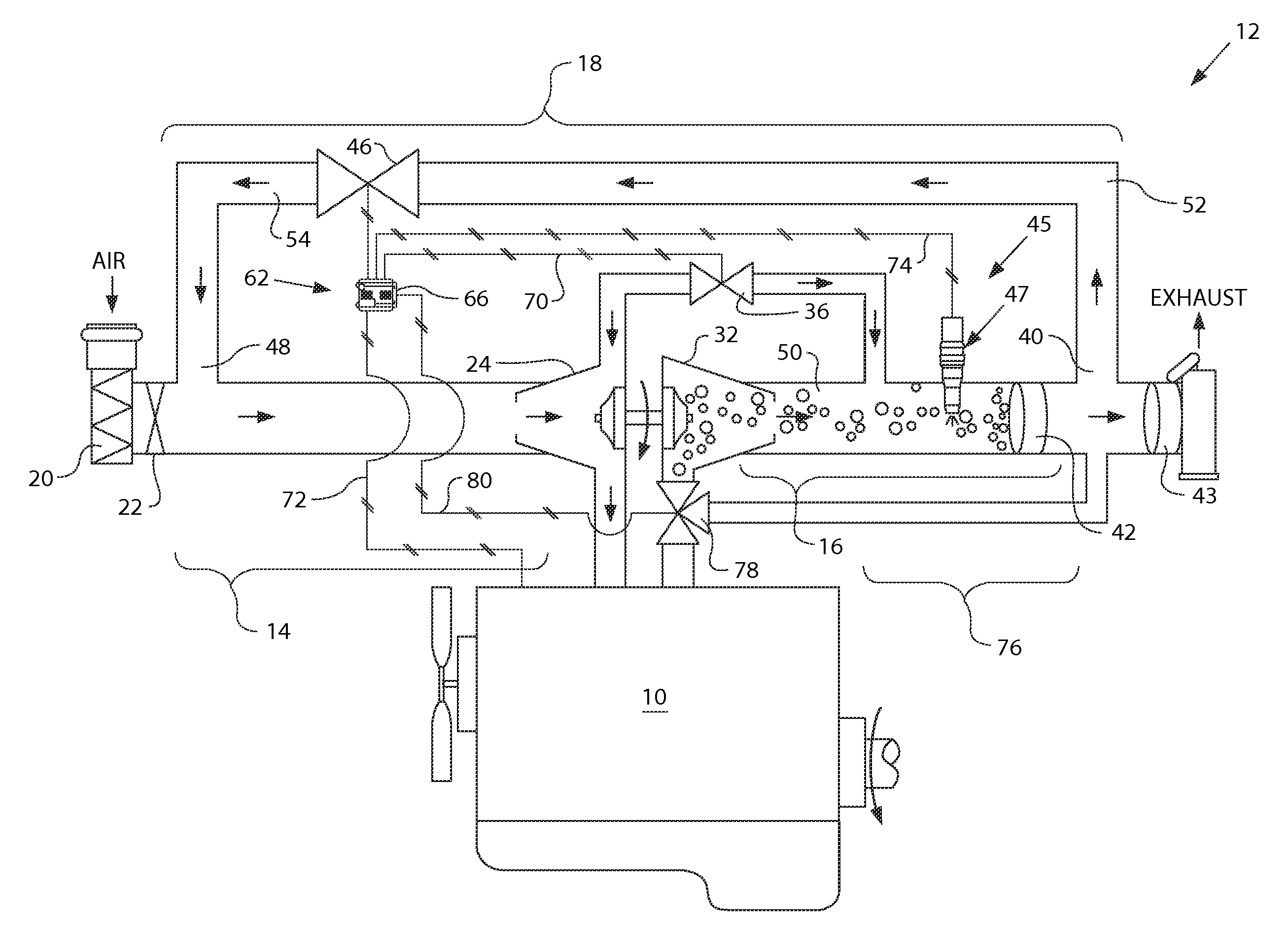
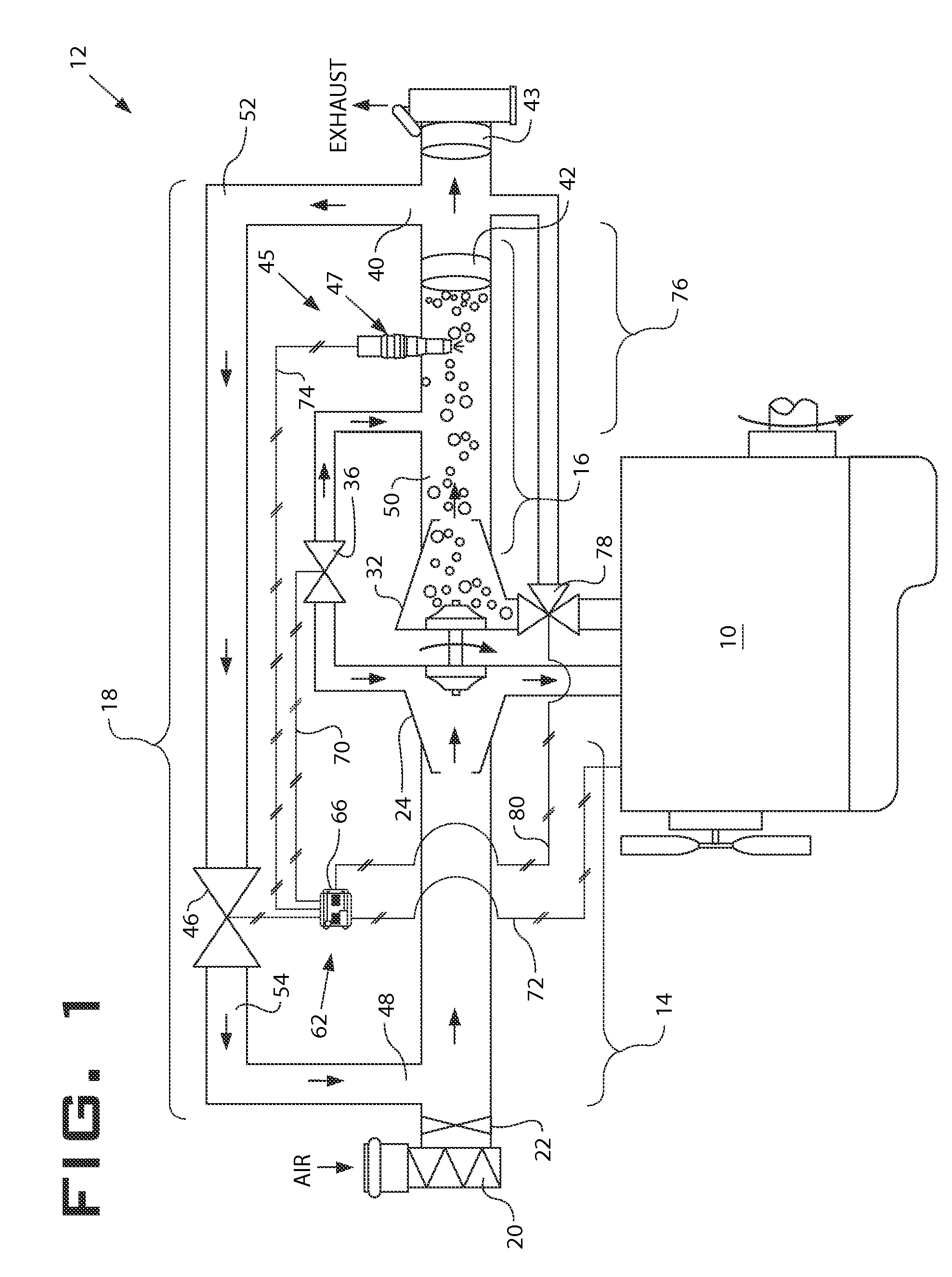
[0013]FIG. 1 illustrates a power source 10 having an exemplary exhaust treatment system 12. Power source 10 may embody an engine such as, for example, a diesel engine, a gasoline engine, a gaseous fuel-powered engine such as a natural gas engine, or any other engine apparent to one skilled in the art. Power source 10 may alternatively embody a non-engine source of power such as a furnace. Exhaust treatment system 12 may include an air induction circuit 14, an exhaust circuit 16, and a recirculation circuit 18 coupled to power source 10 to transfer fluids into and out of power source 10.

[0014]Air induction circuit 14 may include a means for introducing charged air into a combustion chamber (not shown) of power source 10. For example, air induction circuit 14 may include an air cleaner 20 and an induction valve 22 fluidly coupled upstream of one or more compressors 24. It is contemplated that additional and / or different components may be included within air induction circuit 14 such a...


PUM


Abstract

An exhaust treatment system associated with a power source is disclosed. The exhaust treatment system may have a filter located to remove particulate matter from a flow of exhaust, and a regeneration device located proximal the filter. The exhaust treatment system may also have a first fluid handling component located upstream of the power source to vary an amount of oxygen in the flow of exhaust, a second fluid handling component located downstream of the power source to vary the amount of exhaust air flow in the exhaust circuit, and a controller in communication with the regeneration device and the fluid handling component. The controller may determine a need for filter regeneration, and determine adjustments to the first and second fluid handling components required to provide sufficient oxygen and air mass flow in the exhaust for filter regeneration. The controller may further determine an effect the adjustments will have on operation of the power source, and determine corrections for the power source to account for the effects. The controller may substantially simultaneously implement the adjustments and the corrections.

Description

TECHNICAL FIELD [0001]The present disclosure relates generally to an exhaust treatment system and, more particularly, to a method of controlling fuel in an exhaust treatment system that implements temporary engine control.BACKGROUND [0002]Engines, including diesel engines, gasoline engines, natural gas engines, and other engines known in the art, exhaust a complex mixture of air pollutants. The air pollutants may be composed of gaseous and solid material, which include nitrous oxides (NOx) and particulate matter. Due to increased attention on the environment, exhaust emission standards have become more stringent and the amount of NOx and particulate matter emitted from an engine may be regulated depending on the type of engine, size of engine, and / or class of engine.[0003]One method that has been implemented by engine manufacturers to comply with the regulation of NOx exhausted to the environment has been to recirculate exhaust gas from an engine back into the engine for subsequent ...

Claims


Application Information

Patent Timeline
Patent Type & Authority Applications(United States)
IPC IPC(8): F01N9/00F01N3/023
CPCF01N3/0253F01N3/0256F01N3/029F01N3/032F01N3/0842Y02T10/144F02B37/013F02B37/16F02B37/183F02M25/0718Y02T10/121F01N2410/04F02M26/15Y02T10/12
Inventor KAPPAROS, DAVE
Owner CATERPILLAR INC
Why Eureka
Try Eureka