
Methods of forming polycrystalline diamond elements, polycrystalline diamond elements, and earth-boring tools carrying such polycrystalline diamond elements

a technology of diamond elements and diamond elements, which is applied in the field of forming polycrystalline diamond elements, polycrystalline diamond elements, earth-boring tools carrying such polycrystalline diamond elements, can solve the problems of physical or structural weakening of the diamond table, 400° c, and the beginning of thermal degradation, so as to improve the structural integrity and thermal stability

Inactive Publication Date: 2011-02-24
BAKER HUGHES INC
View PDF36 Cites 62 Cited by
  • Summary
  • Abstract
  • Description
  • Claims
  • Application Information

AI Technical Summary

Benefits of technology

[0008]Embodiments of the present disclosure relate to methods of forming polycrystalline diamond elements, such as cutting elements suitable for subterranean

Problems solved by technology

Unfortunately, the presence of a catalyst in the diamond table may lead to thermal degradation commencing at about 400° C. due to differences in the coefficients of thermal expansion (CTEs) of the diamond and the catalyst, and commencing around 700-750° C. due to stimulation of back-graphitization of the diamond to carbon by the catalyst.
It is also known in the art that removal of substantially all of the catalyst from all or a part of the PDC cutting element, such as from a layer adjacent an exposed surface of the PDC cutting element, may result in a physically or structurally weaker portion of the diamond table, which is particularly undesirable in high stress areas, such as proximate a cutting edge of the diamond table.
Consequently, provided the depth of removal of the catalyst is sufficient, the life of the diamond table is extended by reduction in thermal damage and wear, but may be compromised in terms of durability as exemplified by impact resistance.

Method used


Image

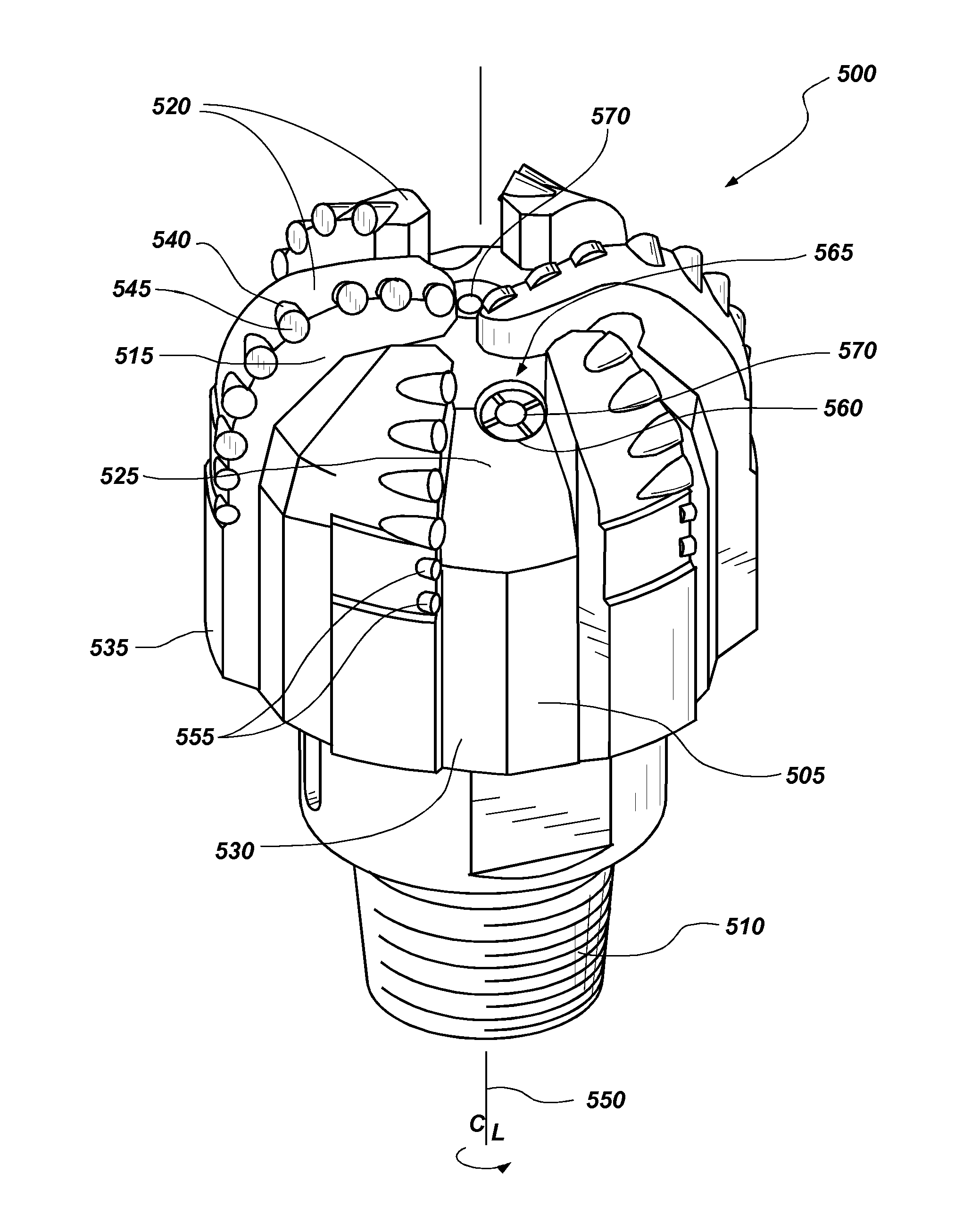
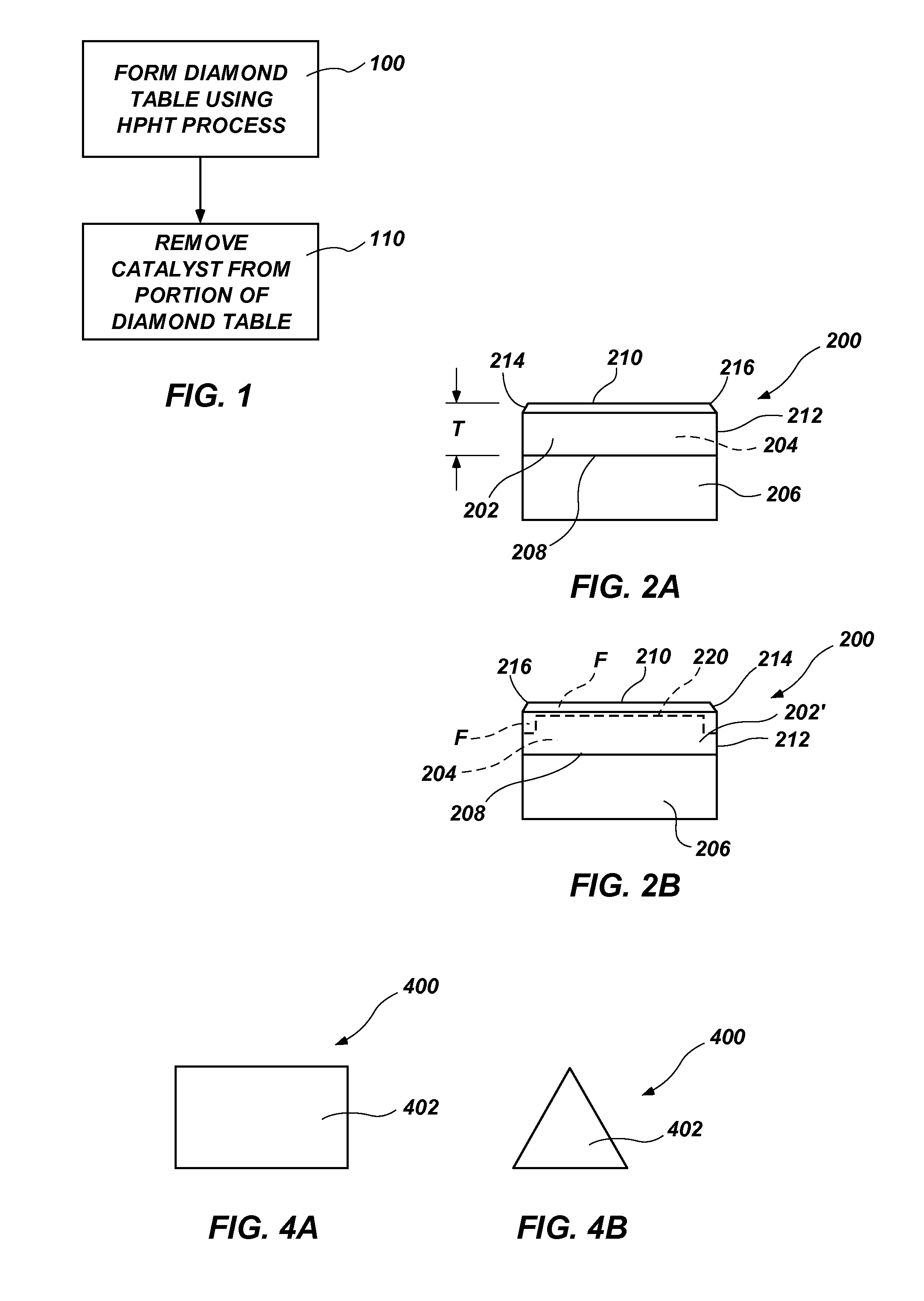
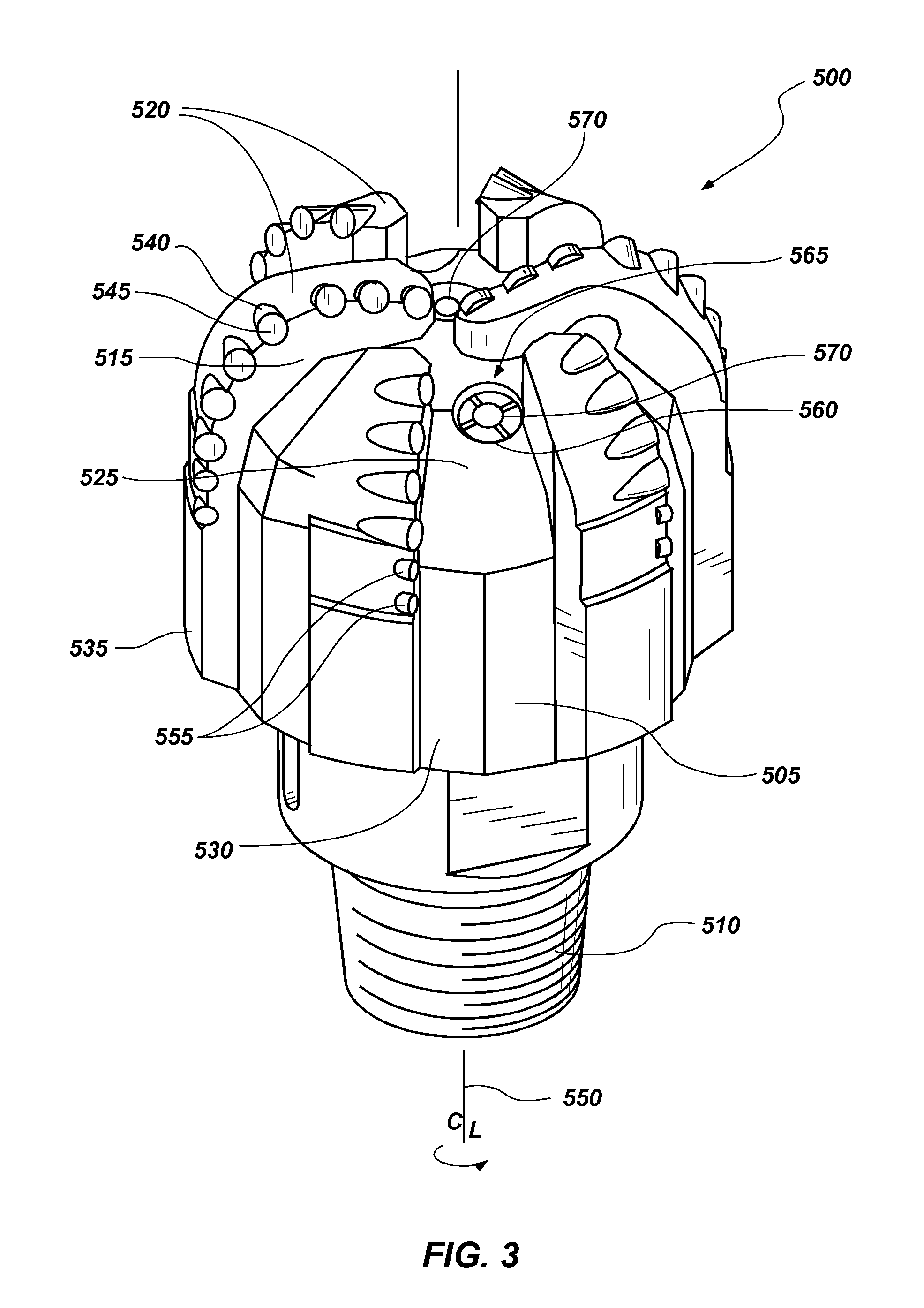
  • Methods of forming polycrystalline diamond elements, polycrystalline diamond elements, and earth-boring tools carrying such polycrystalline diamond elements
  • Methods of forming polycrystalline diamond elements, polycrystalline diamond elements, and earth-boring tools carrying such polycrystalline diamond elements
  • Methods of forming polycrystalline diamond elements, polycrystalline diamond elements, and earth-boring tools carrying such polycrystalline diamond elements

Examples


example 1

[0039]FIGS. 5 and 6 depict the results of drilling operations performed on a subterranean formation with a drill bit carrying polycrystalline diamond elements employed as cutting elements in accordance with an embodiment of the present disclosure and with a drill bit carrying conventional cutting elements. FIG. 5 shows a graph illustrating the results of multiple drilling runs preformed with a drill bit carrying cutting elements with conventional cutting tables that were formed at a pressure of approximately 5.5 GPa. FIG. 5 further shows a similar drilling run completed on the same formation with a drill bit carrying cutting elements with cutting tables that were formed at a pressure of approximately 6.8 GPa in accordance with embodiments of the present disclosure. The graph of FIG. 5 illustrates the distance drilled in each drilling run versus the rate of penetration (ROP) of the drill bit. The distance drilled is presented on the x-axis of the graph and ranges from 4,500 feet to 8...


PUM

PropertyMeasurementUnit
Pressureaaaaaaaaaa
Pressureaaaaaaaaaa
Pressureaaaaaaaaaa

Abstract

Methods of forming polycrystalline diamond elements include forming a polycrystalline diamond element. A Group VIII metal or alloy catalyst is employed to form the polycrystalline diamond compact table at a pressure of at least about 6.5 GPa or greater. The catalyst is then removed from at least a portion of the table to a depth from a working surface thereof, and may be removed from the entirety of the table. Polycrystalline diamond elements include such polycrystalline diamond compact tables. Earth-boring tools include such polycrystalline diamond elements carried thereon and employed as cutting elements.

Description

CROSS-REFERENCE TO RELATED APPLICATIONS[0001]This application claims the benefit of U.S. Provisional Patent Application Ser. No. 61 / 234,776 filed Aug. 18, 2009, the disclosure of which is hereby incorporated herein by this reference in its entirety.TECHNICAL FIELD[0002]Embodiments of the invention relate to methods of forming polycrystalline diamond elements at ultra high pressure, the polycrystalline diamond elements having enhanced structural integrity and thermal stability, to polycrystalline diamond elements formed at ultra high pressure, and earth-boring tools employing such polycrystalline diamond elements as cutting elements.BACKGROUND[0003]Superabrasive cutting elements in the form of Polycrystalline Diamond Compact (PDC) structures have been commercially available for almost four decades, and PDC cutting elements having a polycrystalline diamond compact formed on the end of a supporting substrate for a period in excess of thirty years. The latter type of PDC cutting element...

Claims


Application Information

Patent Timeline
IPC IPC(8): E21B10/46B24D3/10B24D3/06
CPCB22F3/14B24D99/005Y10T428/30E21B10/567C22C26/00B01J3/062B01J2203/062B01J2203/0655B01J2203/0685
Inventor SCOTT, DANNY E.SINOR, L. ALLEN
Owner BAKER HUGHES INC
Learn More