Multi-Layer Radial Power Divider/Combiner

Active Publication Date: 2011-02-24
RAYTHEON CO
View PDF7 Cites 22 Cited by
  • Summary
  • Abstract
  • Description
  • Claims
  • Application Information

AI Technical Summary

Benefits of technology

[0014]In an embodiment, a radial power combiner/divider comprises an RF layer including N planar RF transmission lines radiating from a common port to N ports where N is an integer greater than two. The RF transmission lines are configured to transmit electromagnetic waves centered at a wavelength λc. Each RF transmission line has an electrical length of approximately A*λc/4 where A is an integer. An isolation layer substantially parallel to the RF layer comprises a star resistor having N resistive arms radiating from a common junction, each resistive arm having an electrical length L1 of no greater than λc/4, and N planar isolation transmission lines of electrical length L2 coupled in series to respective resistive arms. Each series pair of a resistive arm and an

Problems solved by technology

A single amplifier chip cannot achieve this level of power without incurring excessive size and power consumption (low efficiency).
However, perfect isolation is never attained because electrically ideal resistors are not possible.
However, even the smallest resistor induces a finite phase that limits isolation of the N ports and corrupts port impedance matching.
Although two-way power divider/combiners are manufactured using planar technology, a significant limitation of a Wilkinson power divider/combiner is that it cannot be designed to take advantage of the lower production costs and other benefits of planar metallization technology for N greater than two.
This configuration preserves the isolation network but is expensive to manufacture and difficult to integrate into an SSPA.
Planar metallization technology has not generally been applied to the N-way Wilkinson combiner because of topological problems that arise in physically locating the isolation res

Method used


Image

  • Multi-Layer Radial Power Divider/Combiner
  • Multi-Layer Radial Power Divider/Combiner
  • Multi-Layer Radial Power Divider/Combiner

Examples


Example

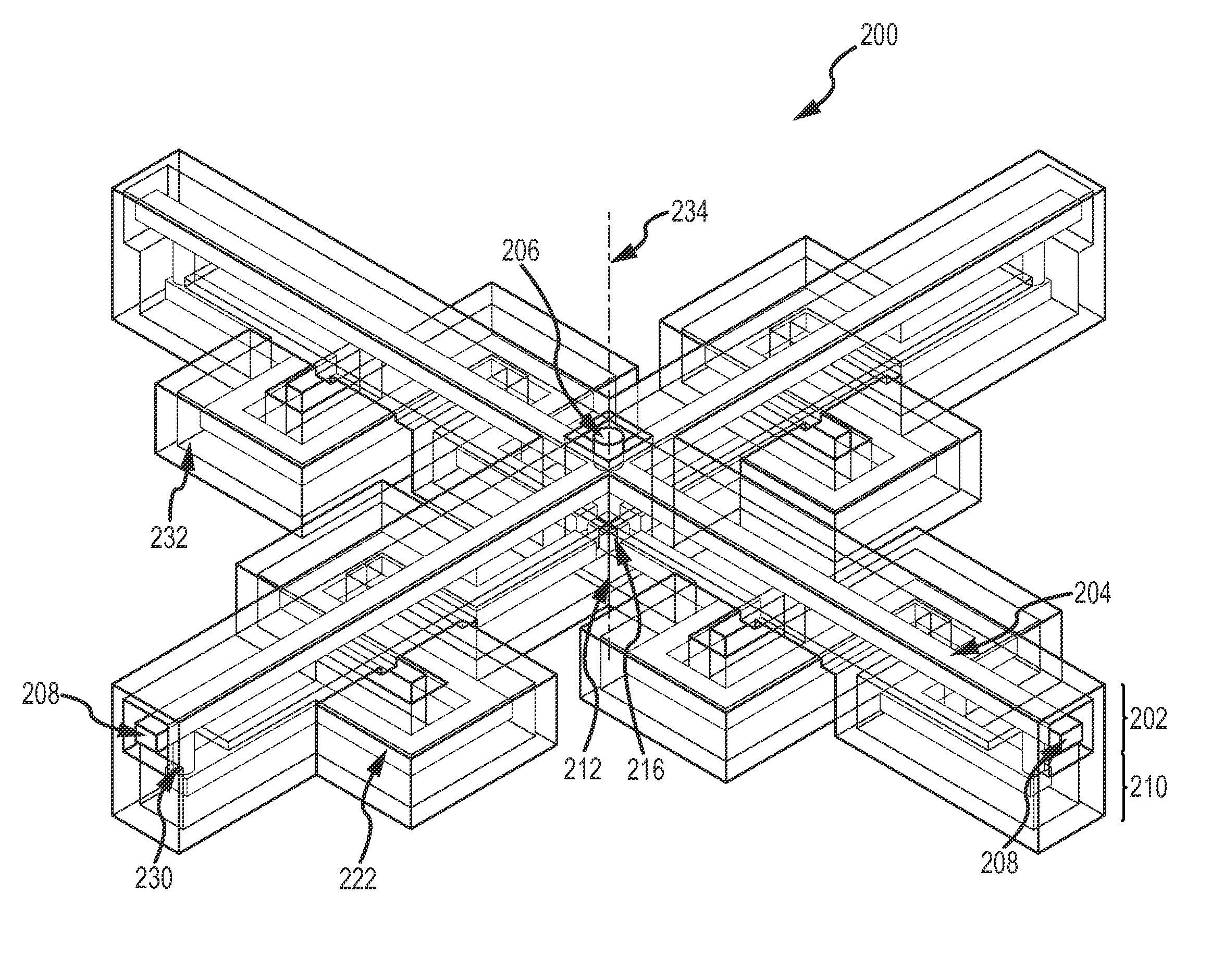
[0026]The present invention provides an N-way radial power divider / combiner with a multi-layer topology without sacrificing the symmetry and phase properties of Wilkinson's isolation network. In fact the proposed multi-layer topology can provide better phase properties than Wilkinson's thereby improving the isolation and higher power handling because it can use physically larger resistors. The radial power divider / combiner's isolation network is preferably configured so that separate paths are separated by an approximately zero phase angle at the center frequency to maximize path isolation. The multi-layer structure may be fabricated using low-cost planar metallization technologies. The divider / combiner may be used over a wavelength range of approximately 30 to 0.1 cm (approximately 1 GHz to 300 GHz) and higher frequencies as SSPA technology evolves.

[0027]As shown in a schematic illustration in FIG. 6, a radial power combiner / divider 100 comprises an RF layer 102 including N planar ...


PUM


Abstract

An N-way multi-layer radial power combiner/divider comprises an RF layer including N planar RF transmission lines radiating from a common port to N ports. An isolation layer substantially parallel to the RF layer comprises a star resistor having N resistive arms radiating from a common junction and N planar isolation transmission lines coupled in series to respective resistive arms. Each series pair of a resistive arm and an isolation transmission line is ideally a half-wavelength in electrical length. N vertical interconnects between the RF layer and the isolation layer connect the ends of the N isolation transmission lines to the ends of the N RF transmission lines at the N individual ports, respectively. Any path from one individual port through the common junction of the star resistor to another individual port is approximately a full wavelength λc or multiple thereof so that the phase angle through the isolation network is approximately zero degrees. This approach can achieve better isolation and power handling than the Wilkinson design while employing the benefits of planar metallization technology.

Description

BACKGROUND OF THE INVENTION[0001]1. Field of the Invention[0002]This invention relates to radial power divider / combiners for use in solid-state power amplifiers (SSPAs), and more particularly to a multi-layer topology that realizes the cost benefits of planar fabrication without compromising the isolation characteristics of a Wilkinson divider / combiner for N-way devices where N is greater than two.[0003]2. Description of the Related Art[0004]Solid state power amplifier (SSPAs) modules are comprised of N identical amplifier devices that are combined into a single amplifier structure using a passive divider / combiner. SSPAs have a variety of uses. For examples, SSPAs may be used in satellites to provide transmit power levels sufficient for reception at ground-based receivers, or to perform the necessary amplification for signals transmitted to other satellites in a crosslink application. SSPAs are also suitable for ground-based RF applications requiring high output power such as cellul...

Claims


Application Information

Patent Timeline
IPC IPC(8): H01P5/12
CPCH01P5/16H01P5/12
Inventor HUETTNER, STEVEN E.
Owner RAYTHEON CO
Why Eureka
Try Eureka