
Twin-monitor electronic display system

a display system and electronic display technology, applied in image enhancement, instruments, ultrasonic/sonic/infrasonic diagnostics, etc., can solve the problems of reducing the size, unable to maintain the entire display image, and setting a medical examination is hardly feasible or acceptabl

Active Publication Date: 2011-02-24
SUPER SONIC IMAGINE
View PDF7 Cites 59 Cited by
  • Summary
  • Abstract
  • Description
  • Claims
  • Application Information

AI Technical Summary

Benefits of technology

[0017]With such a display system, display of the ultrasound image such as acquired can be guaranteed with maximum definition and maximum size on the first monitor, together with the display of the image adapted for processing the acquired image in lower definition and / or reduced size.
[0045]This characteristic allows very easy manipulation of three-dimensional volumes, even though the two-dimensional images from which they are generated still remain displayed in large format on the main monitor. The touch-screen is also particularly well adapted to the manipulating of volumes in space using most ergonomic, natural hand movements.

Problems solved by technology

The major drawback with these electronic display systems is that it is necessary to reduce the size of the ultrasound image displayed in full-screen format, either by changing the scale of or by cropping the image, so that it is possible to display the graphical elements used to perform processing of the displayed ultrasound image.
It is therefore not possible to maintain the entirety of the displayed image or to maintain maximum resolution for this image.
This effectively guarantees good image quality, but compels the user to give attention simultaneously to two monitors, which in the setting of a medical examination is hardly feasible or acceptable.

Method used


Image

  • Twin-monitor electronic display system
  • Twin-monitor electronic display system
  • Twin-monitor electronic display system

Examples


Embodiment Construction

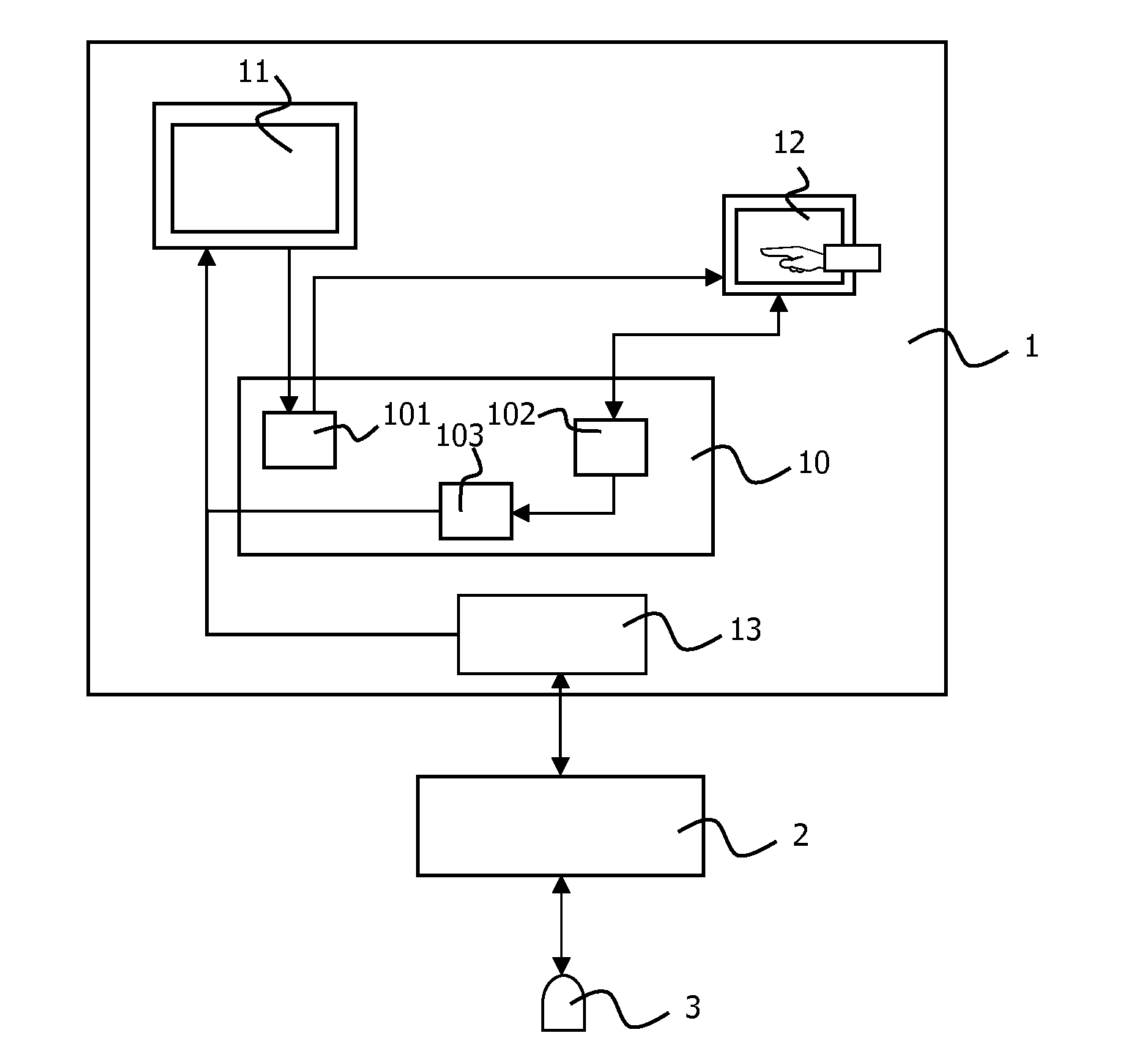
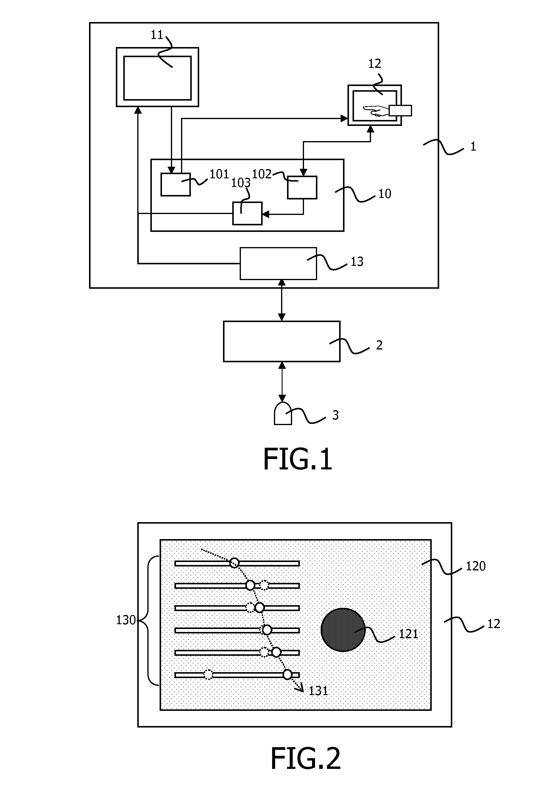
[0066]FIG. 1 schematically illustrates an electronic display system 1 according to the invention. This electronic display system 1 is coupled to ultrasound imaging equipment 2 capable of capturing an image of a medium using a probe 3.

[0067]According to the invention, the electronic display system 1 comprises at least one processing module 10 and two display monitors 11 and 12 of which one, display unit 12, is a touch-screen. The touch-screen 12 can be a single or multi-touch screen.

[0068]The processing module 10 comprises at least one sub-module for duplication 101 of the ultrasound image such as acquired using the ultrasound imaging equipment 2 and displayed on the first monitor 11. These duplication 101 means send the duplicate to the second touch-screen monitor 12 on which it is displayed at least in part.

[0069]Such a duplicate is obtained using known means, for example partial display of a previous screen capture on the main monitor, or by saving and recopying in a buffer memory...


PUM


Abstract

The invention concerns an electronic display system, intended to be coupled with ultrasound imaging equipment capable of capturing an image of a medium, said system comprising a first monitor to display an ultrasound image such as captured by the ultrasound imaging equipment and image processing means. According to the invention, the system further comprises a second touch-screen monitor, means to duplicate the ultrasound image, means to send this duplicate to the second monitor on which at least part therefore is displayed, means to display at least one graphical element which, by means of the tactility of the screen, is used to perform at least one processing operation on the ultrasound image, means for instant application of all processing operations performed using the second monitor to the duplicate ultrasound image displayed on the second monitor, and means for instant or deferred application to the ultrasound image displayed on the first monitor of all or part of the processing operations performed on the duplicate ultrasound image by means of the second monitor.

Description

BACKGROUND OF THE INVENTION[0001]The present invention relates to the general area of electronic systems for displaying images in general, and more particularly to those intended to be coupled with ultrasound imaging equipment capable of capturing an image of a medium.[0002]In general, such electronic display systems comprise a monitor to display the ultrasound image such as captured by the ultrasound imaging equipment. These electronic display systems comprise image processing means, or are connected to processing means.[0003]Such electronic display systems are known to persons skilled in the art, for example through documents U.S. Pat. No. 6,063,030, U.S. Pat. No. 6,468,212 and U.S. Pat. No. 7,022,075.[0004]These patent documents describe display systems comprising a single viewing monitor. This single monitor defines a display space which is shared by the ultrasound image and by the graphical elements used to perform processing of the ultrasound image.[0005]The major drawback wit...

Claims


Application Information

Patent Timeline
IPC IPC(8): G09G5/00G06F3/0484G06F3/0488
CPCG06F3/04847G06F3/0488G06F3/04883G06F3/1423G06T7/0012G06T2200/24G06F3/04842G06T2207/30004G09G2340/12A61B8/464A61B8/467A61B5/7445G06F3/04812G06T2207/10132A61B8/468A61B8/469G06F3/041
Inventor RONCALEZ, PASCALLANEYRIE, PIERRE-LIN
Owner SUPER SONIC IMAGINE
Learn More