Liquid crystal display device, black matrix substrate and color filter substrate

a liquid crystal display device and black matrix technology, applied in the field of liquid crystal display devices, can solve the problems of increasing the thickness of the liquid crystal display device, and affecting the operation of the touch panel

Inactive Publication Date: 2011-02-24
TOPPAN PRINTING CO LTD
View PDF12 Cites 114 Cited by
  • Summary
  • Abstract
  • Description
  • Claims
  • Application Information

AI Technical Summary

Benefits of technology

[0020]A liquid crystal display device according to a first embodiment of this invention includes a first substrate, a second substrate located opposite the first substrate via a liquid crystal, a blue display element, a green display element, a red display element, a short-wavelength optical sensor, a red optical sensor, and an infrared optical sensor formed on a liquid crystal side surface of the first substrate, and a colo...

Problems solved by technology

In the liquid crystal display device provided in a mobile device such as a cellular phone or a portable small-sized personal computer, inputting via a keyboard is difficult.
However, the touch panel installed on the liquid crystal display device increases the thickness of the liquid crystal display device.
In particular, in the liquid crystal display device in the mobile device, light loss attributed to the touch panel may occur, such as surface reflection or loss of transmitted light.
This may degrade the quality of liquid crystal display images.
However, when a viewer watches television with such the transmissive liquid crystal display device at night or in a dark place, the screen may be too bright and difficult to see.
Furthermore, in the transmissive liquid crystal display device, the light source on the rear surface accounts for about 80% of power consumption.
Thus, a reduction in power consumption has been a major challenge.
In the document 2, an error in a user's touch with a liquid crystal screen may result from the influence of the intensity of external light or backlight luminance.
Furthermore, the document 2 describes an arrangement of a first optical sensor and ...

Method used


Image

  • Liquid crystal display device, black matrix substrate and color filter substrate
  • Liquid crystal display device, black matrix substrate and color filter substrate
  • Liquid crystal display device, black matrix substrate and color filter substrate

Examples


first embodiment

[0049]In the present embodiment, a liquid crystal display device will be described which is capable of receiving optical signals and which suppresses the adverse effect of an external light condition on display quality, the liquid crystal display device reducing malfunction.

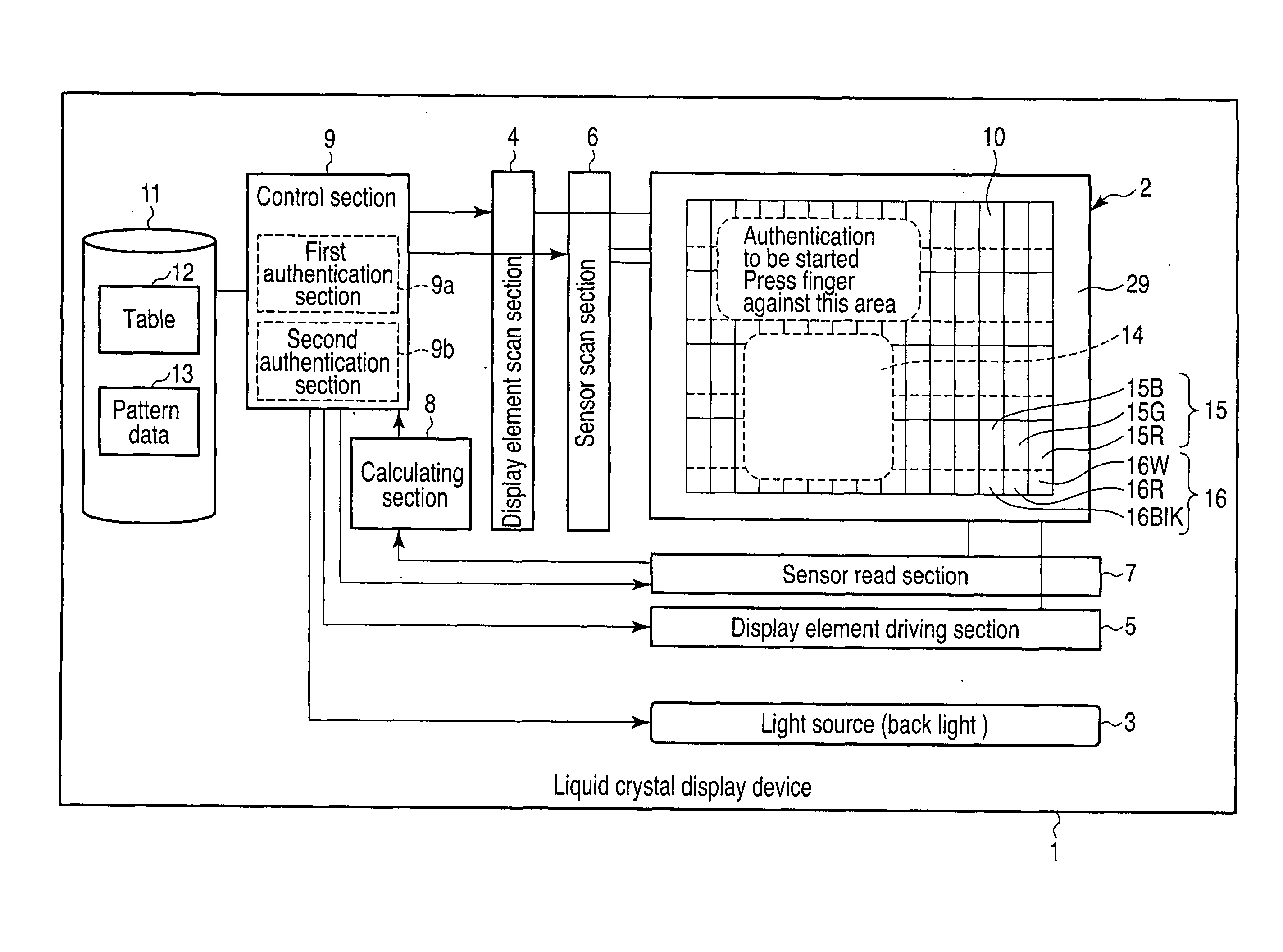
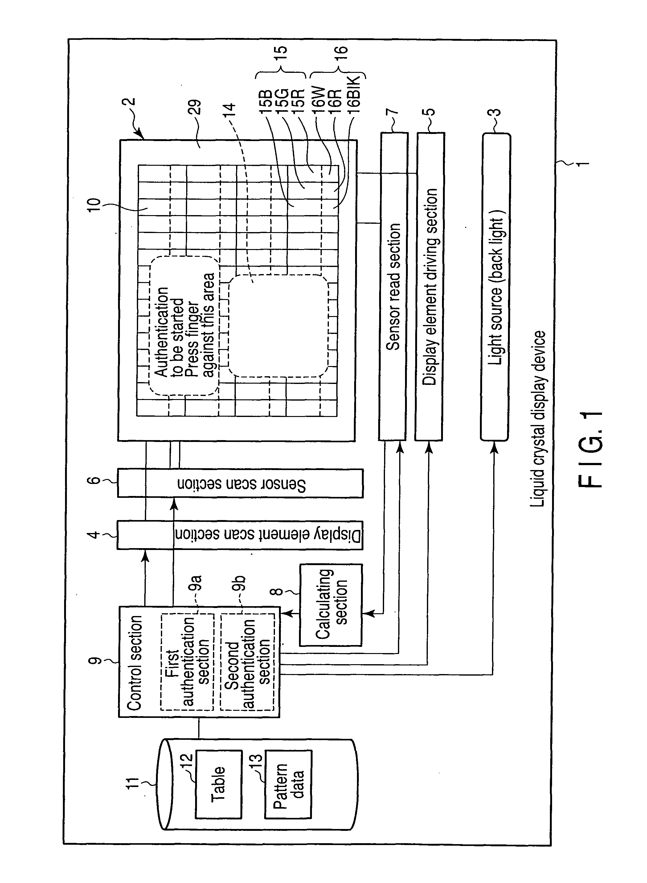
[0050]FIG. 1 is a block diagram showing an example of the liquid crystal display device according to the present embodiment.

[0051]The liquid crystal display device 1 according to the present embodiment comprises a light source 3 in the rear of a display screen section 2 (the display screen section 2 is shown at the bottom of FIG. 1 for easy understanding). The light source 3 emits light with three wavelengths for blue, green, and red. For example, the light source 3 may be a fluorescent lamp or LED elements of three-wavelength light emission type, or organic EL elements of a surface light emission type.

[0052]A display element scan section 4, a display element driving section 5, a sensor scan section 6, and a sens...

second embodiment

[0167]In the present embodiment, a modification of the above-described first embodiment in which an infrared transmission filter is formed of a stack of a plurality of filters will be described.

[0168]FIG. 13 is a sectional view showing an example of a light detection pixel provided in a liquid crystal display device according to the present embodiment.

[0169]In the present embodiment, an infrared transmission filter 30Blk is formed of a stack of a red filter 31 and a blue filter 32.

[0170]In the present embodiment, a plurality of openings 33 through which light enters the pixel are formed in a substrate 25. The openings 33 are located opposite the infrared transmission filter 30Blk, a red filter 18R, and a short-wavelength transmission filter 18W via a liquid crystal 22, respectively. Optical sensors 20Blk, 20R, and 20W each receive light to be observed, via the plurality of openings 33, a liquid crystal 22, and a corresponding one of the infrared transmission filter 30Blk, red filter...

third embodiment

[0172]In the present embodiment, description will be given of a modification of the first and second embodiments in which a liquid crystal display device comprises a light detection pixel 16 further including a yellow pixel.

[0173]FIG. 14 is a block diagram showing an example of a liquid crystal display device according to the present embodiment.

[0174]A liquid crystal display device 30 according to the present embodiment comprises a light source 3 behind a display screen section 31. A display element scan section 4, a display element driving section 5, a sensor scan section 6, and a sensor read section 7 are electrically connected to the display screen section 31.

[0175]The display screen section 31 comprises a color filter 32. In the present embodiment, display pixels 33 and light detection pixels 34 are disposed in the display area of the display screen section 31. The light detection pixels 34 are arranged on the display screen at almost equal intervals.

[0176]The display element sc...


PUM


Abstract

A liquid crystal display device includes a first substrate, a second substrate located opposite the first substrate via a liquid crystal, a blue display element, a green display element, a red display element, a short-wavelength optical sensor, a red optical sensor, and an infrared optical sensor formed on a liquid crystal side surface of the first substrate, and a color filter formed between the first substrate and the second substrate and includes a blue filter, a green filter, a first red filter, a short-wavelength transmission filter, a second red filter, and an infrared transmission filter corresponding to the blue display element, the green display element, the red display element, the short-wavelength optical sensor, the red optical sensor, and the infrared optical sensor, respectively.

Description

CROSS-REFERENCE TO RELATED APPLICATIONS[0001]This application is based upon and claims the benefit of priority from prior Japanese Patent Applications No. 2009-191326, filed Aug. 20, 2009; and No. 2010-113591, filed May 17, 2010, the entire contents of both of which are incorporated herein by reference.BACKGROUND OF THE INVENTION[0002]1. Field of the Invention[0003]The present invention relates to a liquid crystal display device including an optical sensor, and a black matrix substrate and a color filter substrate provided in the liquid crystal device.[0004]2. Description of the Related Art[0005]An active-matrix liquid crystal display device drives a liquid crystal using thin-film transistors, for example, amorphous silicon TFTs (Thin Film Transistors) or polysilicon TFTs. The liquid crystal display device is used in various devices including a mobile device such as a cellular phone, and a large-sized television.[0006]The liquid crystal display device cannot emit light itself and ca...

Claims


Application Information

Patent Timeline
IPC IPC(8): G06F3/042G09G5/00
CPCG02F1/133512G02F2001/13396G06F3/042G06F3/0412G02F1/133514G02F2001/13312G02F1/13312G02F1/13396
Inventor HAGIWARA, HIDESATOFUKUYOSHI, KENZO
Owner TOPPAN PRINTING CO LTD
Why Eureka
Try Eureka