Light emitting device

Inactive Publication Date: 2011-02-24
THE UNIV OF TOKYO
View PDF8 Cites 13 Cited by
  • Summary
  • Abstract
  • Description
  • Claims
  • Application Information

AI Technical Summary

Benefits of technology

[0050]In the light emitting device of the invention, the laser oscillation can easily

Problems solved by technology

However, in each proposal, only spontaneous light emission from the Si crystal can be

Method used


Image

  • Light emitting device
  • Light emitting device
  • Light emitting device

Examples


first embodiment

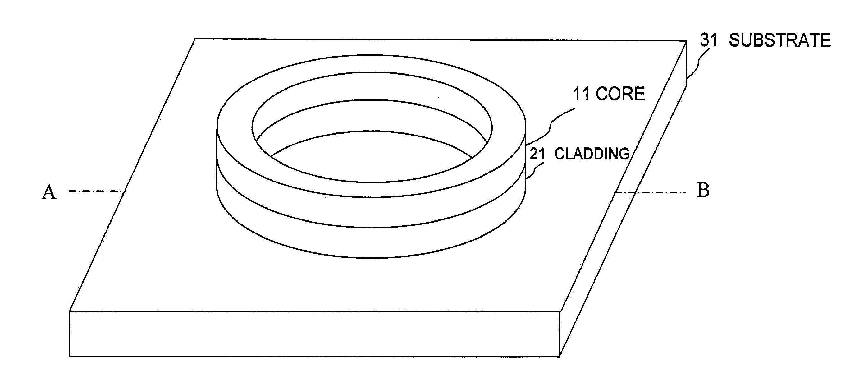
[0084]A light emitting device according to a first embodiment of the invention includes a ring optical resonator laminated on a substrate, and the light emitting device of the first embodiment is characterized in that the optical resonator includes: a core that is made of a semiconductor through which light propagates; and a cladding that is laminated on at least the substrate side in the substrate side of a lamination direction with respect to the core and a side opposite the substrate side, at least a ring inner circumference side and a ring outer circumference side of the core are covered with a space or a transparent body whose refractive index is lower than that of the cladding, and a ring inner circumference side and a ring outer circumference side of the cladding are partially covered with the space or the transparent body whose refractive index is lower than that of the cladding.

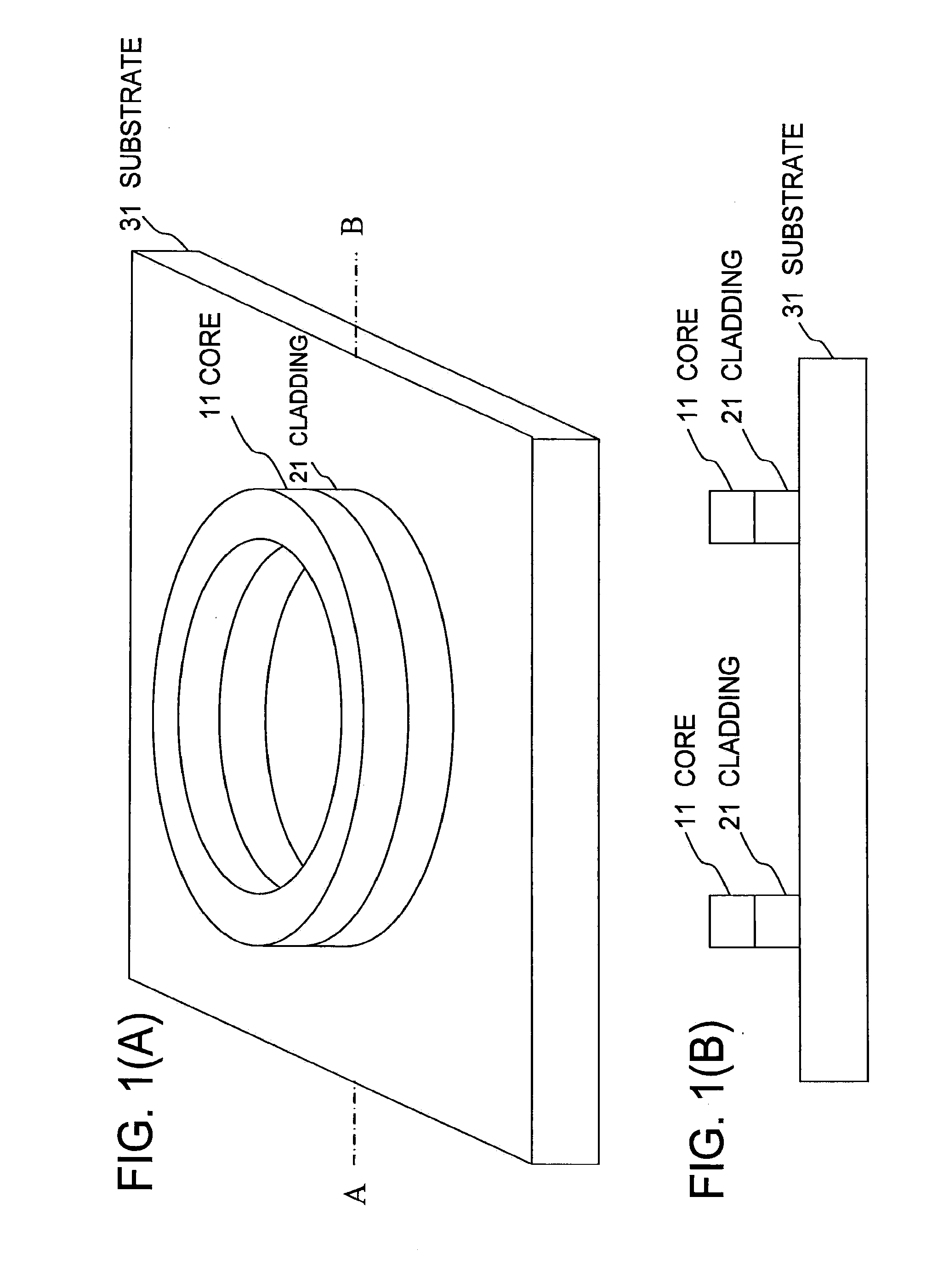
[0085]FIG. 1(A) is a perspective view of a light emitting device of the first embodiment, and FIG...

example

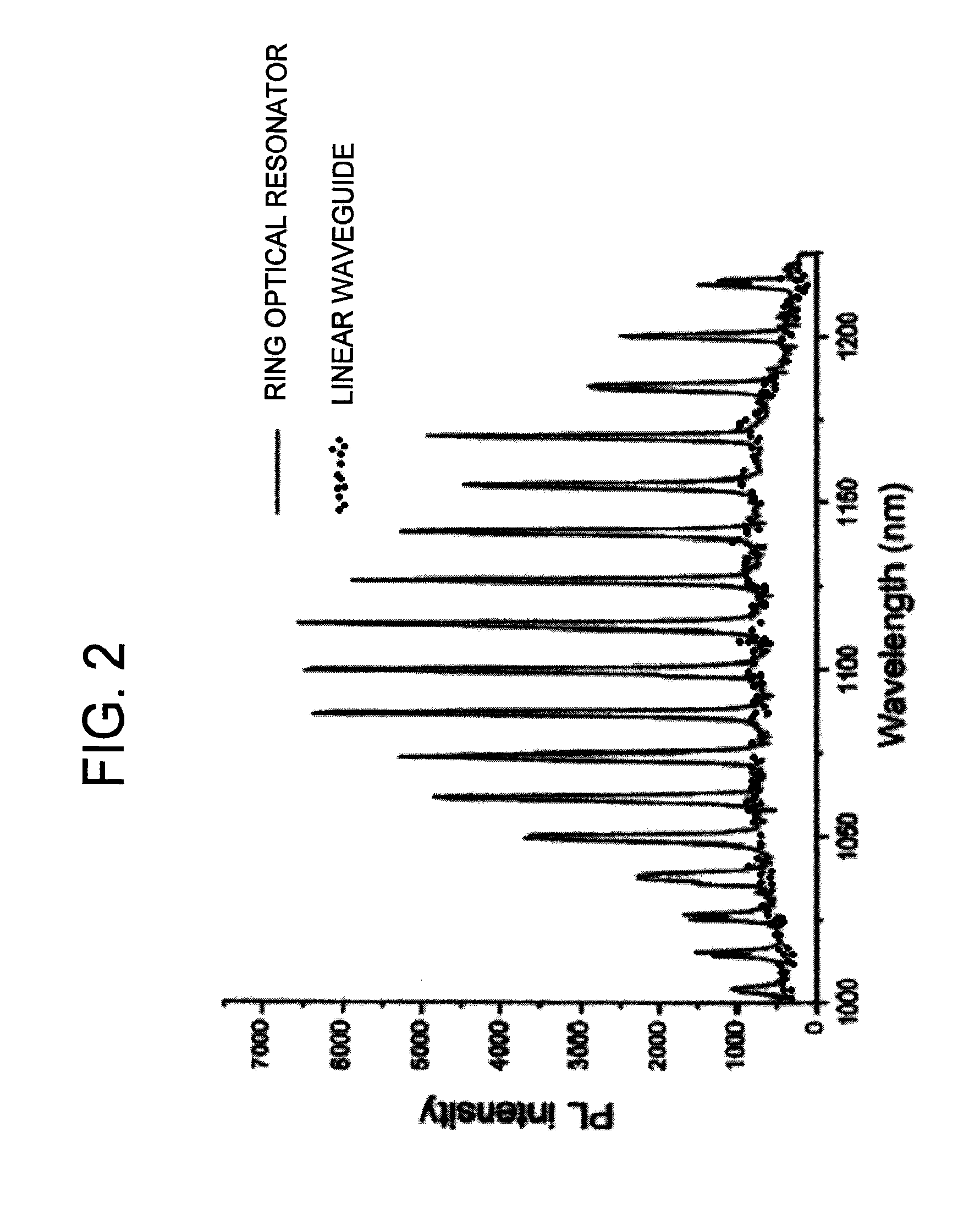
[0088]As illustrated in FIG. 1, a light emitting device according to an example has a structure in which a ring optical resonator is formed by the core 11 and cladding 21 on the substrate 31. The substrate 31 is made of Si, the core 11 is made of Si, and the cladding 21 is made of SiO2. The spaces are formed on the ring outer circumference sides and ring inner circumference sides of the core 11 and cladding 21 and the upper surface of the core 11. The ring has a radius of 300 nm, the core has a width of 300 nm, and the core has a thickness of 340 nm. The light emitting device of the example has this structure and the electrode structure in which the electrons and holes are externally injected. In FIG. 1, an electrode structure is omitted. FIG. 2 illustrates result in which, in order to explain a basic operation, charges are locally injected in the ring optical resonator to measure dependence of emission intensity on a wavelength. In FIG. 2, an upper side expresses the ring optical r...

second embodiment

[0108]A light emitting device according to a second embodiment of the invention includes a ring optical resonator in which the Ge core and the Si cladding are combined. Because of the small refractive index difference between the Ge core and the Si cladding, the loss is increased by C. the dissipation of the spontaneous emission light from the core. The evanescent wave radiation from the core to the cladding is also increased. The loss due to E. evanescent wave radiation is reduced by over etching of the cladding. FIG. 3(A) is a perspective view of the light emitting device having the structure of the second embodiment, and FIG. 3(B) is a sectional view taken on a line A-B of FIG. 3(A). In the direction parallel to a substrate surface of a cladding 22, a width on the side of the core 11 is wider than a width on the side opposite from the core 11. Therefore, the leakage of the evanescent wave from the core 11 to the cladding 22 can be reduced, and the bending loss caused by the coupl...


PUM


Abstract

A light-emitting device having a ring optical resonator and capable of laser oscillation by a novel structure realized by working out the mechanism of light emission. The light-emitting device having a ring optical resonator fabricated on a base is characterized in that the optical resonator has a core made of a semiconductor and serving to propagate light and a clad formed on at least the base side of the core in the stack direction out of the base side and the opposite side of the core, at least the ring inner and outer peripheral surfaces of the core are covered with a transparent body having an index of refraction lower than that of the space or the clad, and a part of the ring inner and outer peripheral surfaces of the clad are covered with a transparent body having an index of refraction lower than that of the space or the clad.

Description

TECHNICAL FIELD[0001]The present invention relates to a light emitting device that emits light by utilizing a ring optical resonator. Particularly the invention relates to a laser light emitting device in which a semiconductor technology is utilized.BACKGROUND ART[0002]In a recent semiconductor integrated circuit, much higher-speed signal processing is required, and a laser light emitting device is being used to transmit the signal between circuits. Particularly in a semiconductor integrated circuit, there is a strong demand for implementing a Si or Ge laser light emitting device that can be formed on a Si or Ge based semiconductor substrate. Therefore, there has been made a proposal in which a Si nanocrystal is used (see Patent Document 1) or a proposal in which the light is emitted by utilizing a Si waveguide on the Si substrate.[0003]However, in each proposal, only spontaneous light emission from the Si crystal can be confirmed, and the laser oscillation is not achieved yet by ut...

Claims


Application Information

Patent Timeline
IPC IPC(8): H01S5/10H01S5/12
CPCH01S5/021H01S5/1032H01S5/3224H01S5/1075H01S5/12H01S5/1071
Inventor WADA, KAZUMILIN, SHIYUNKOBAYASHI, YOSUKELIM, PENG HUEI
Owner THE UNIV OF TOKYO
Why Eureka
Try Eureka