MRI compatible electrode circuit

a technology of electrode circuits and compatible electrodes, applied in the field of medical devices, can solve the problems of high current density in the tissue, and patients' safety risks, and achieve the effect of reducing the rf-induced heating of the tissu

Active Publication Date: 2011-02-24
IMRICOR MEDICAL SYST
View PDF37 Cites 30 Cited by
  • Summary
  • Abstract
  • Description
  • Claims
  • Application Information

AI Technical Summary

Benefits of technology

[0010]It is an object of the invention to provide an improved device and method for reducin...

Problems solved by technology

Each of the three fields associated with MRI presents safety risks to patients when a medical device is in close proximity to or in contact either externally or internally with patient tissue.
One important safety risk is the heating that can result from an interaction between the RF field of the MRI scanner and the medical device (RF-induced heating), especially medical devices which have elongated conductive structures with tissue contacting electrodes, such as electrode wires in pacemaker and implantable cardioverter defibrillator (ICD) leads, guidewires, and catheters.
The RF-induced heating safety risk associated with electrode wires in the MRI environment results from a coupling between the RF field and the electrode wire.
RF currents induced in the electrode wire may be delivered through the electrode into the tissue, resulting in a high current density in the tissue and associated Joule or Ohmic tissue heating.
Also, RF induced currents in the electrode wire may result in increased local specific absorption of RF energy in nearby tissue, thus increasing the tissue's temperature.
In addition, RF induced currents in the electrode wire may cause Ohmic heating in the electrode wire, itself, and the resultant heat may transfer to the patient.
Notwithstanding the foregoing attempts to reduce RF-induced heating, significant issues remain.
For example, high impedance electrode wires limit the functionality of the electrode wire and do not allow for effective ablation, pacing...

Method used


Image

  • MRI compatible electrode circuit
  • MRI compatible electrode circuit
  • MRI compatible electrode circuit

Examples


Embodiment Construction

[0035]In describing the invention herein, reference is made to an exemplary lead assembly comprising a catheter. However, as will be appreciated by those skilled in the art the present invention may be used with any implantable medical device. By implantable we mean permanently as with cardiac pacemakers, defibrillators and neurostimulators; or temporarily implantable such as in interventional procedures and including by way of example cardiac ablation devices and the like. Further the exemplary lead assembly may be used external to the body but still be in contact with body tissue such as the skin. Also as used herein, an electrode wire is any conductive structure that is in electrical contact with an electrode. Typically, an electrode wire is an actual wire; however, an electrode wire may also be a circuit board trace, a conductive lumen, or any material which conducts electricity.

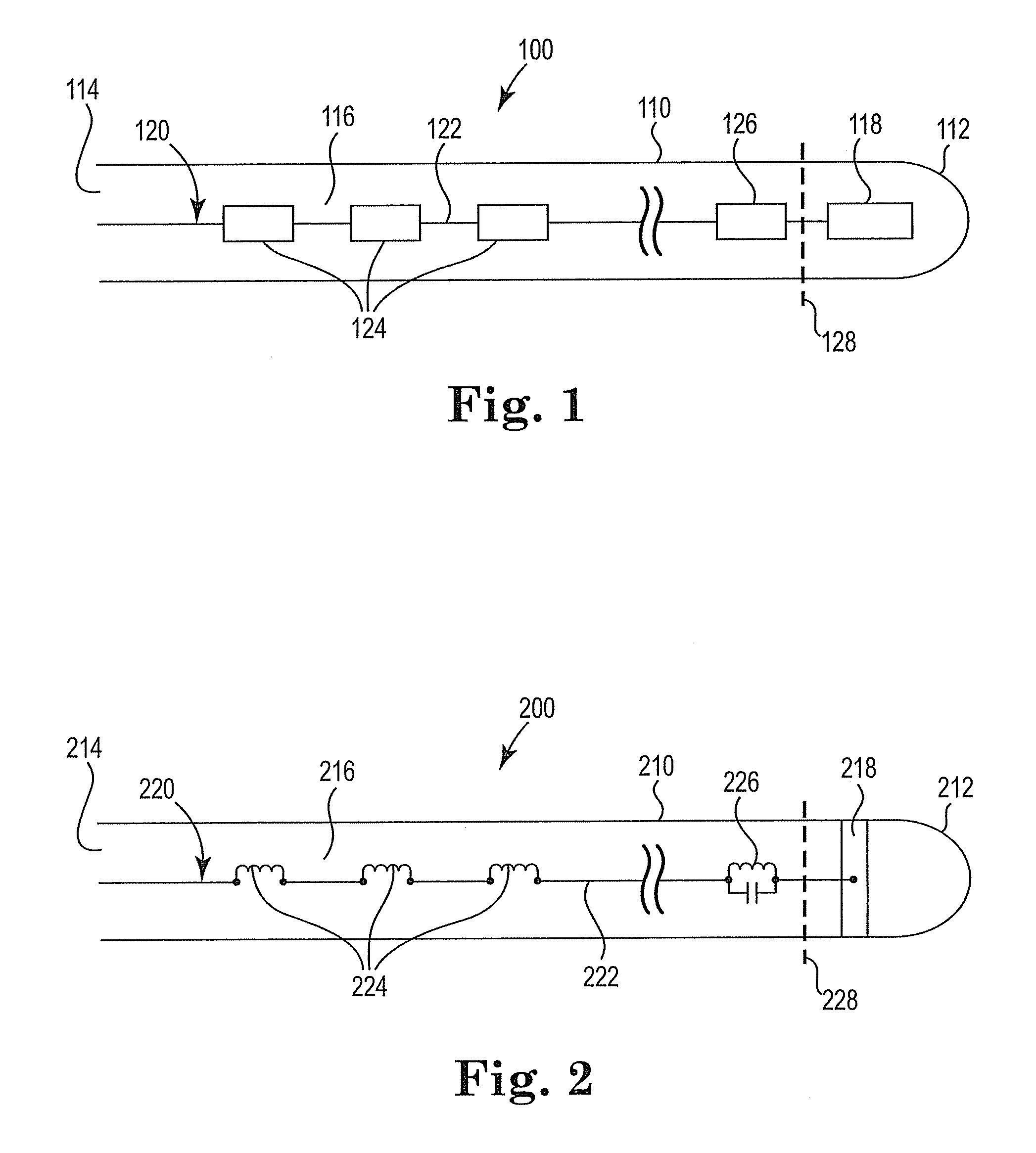
[0036]FIG. 1 is a block diagram illustrating the lead assembly 100 in its simplest form in accordance...


PUM

PropertyMeasurementUnit
Lengthaaaaaaaaaa
Magnetic fieldaaaaaaaaaa

Abstract

An MRI compatible electrode circuit construct is provided. The construct includes at least two filter components constructed from an electrode wire. One filter component may be a resonant LC filter at or near an electrode/wire interface that resolves the issue of insufficient attenuation by effectively blocking the RF induced current on the wire from exiting the wire through the electrode. The second filter component may include one or more non-resonant filter(s) positioned along the length of the electrode wire that resolve(s) the issue of excessive heating of the resonant LC filter by significantly attenuating the current induced on the wire before it reaches the resonant LC filter. The non-resonant filter(s) may also attenuate the RF current reflected from the resonant LC filter thereby resolving the issue of the strong reflected power from the resonant filter and the associated dielectric heating.

Description

FIELD OF THE INVENTION[0001]The invention relates to medical devices with tissue contacting electrodes used in the magnetic resonance imaging (MRI) environment and in particular to a method and device for attenuating electromagnetic fields applied to such devices during MRI scanning.BACKGROUND OF THE INVENTION[0002]MRI has achieved prominence as a diagnostic imaging modality, and increasingly as an interventional imaging modality. The primary benefits of MRI over other imaging modalities, such as X-ray, include superior soft tissue imaging and avoiding patient exposure to ionizing radiation produced by X-rays. MRI's superior soft tissue imaging capabilities have offered great clinical benefit with respect to diagnostic imaging. Similarly, interventional procedures, which have traditionally used X-ray imaging for guidance, stand to benefit greatly from MRI's soft tissue imaging capabilities. In addition, the significant patient exposure to ionizing radiation associated with tradition...

Claims


Application Information

Patent Timeline
IPC IPC(8): A61N1/00H01S4/00
CPCA61B5/0422A61B5/055A61B18/1492Y10T29/49002A61N2001/086A61N1/08Y10T29/49117A61B2017/00911A61N1/086A61B5/287A61B5/05
Inventor LLOYD, THOMAS W.WEDAN, STEVEN R.STENZEL, GREGG S.
Owner IMRICOR MEDICAL SYST
Why Eureka
Try Eureka