MRI compatible cable

Active Publication Date: 2013-08-08
IMRICOR MEDICAL SYST
View PDF1 Cites 1 Cited by
  • Summary
  • Abstract
  • Description
  • Claims
  • Application Information

AI Technical Summary

Benefits of technology

This patent describes a method for reducing the heating of tissue caused by RF current in cables used to connect peripheral equipment to a patient's skin during MRI scans. The invention also introduces a new cable design that is flexible, easy to move around, and has a unique filtering system to prevent current from being induced on the lead assembly. The cable structure is also designed to be physically stable and minimize the size of the filtering components. These technical effects improve the safety and efficiency of MRI procedures.

Problems solved by technology

Each of the three fields associated with MRI presents safety risks to patients when a medical device is in close proximity to or in contact either externally or internally with patient tissue.
One important safety risk is the heating that can result from an interaction between the RF field of the MRI scanner and the medical device (RF-induced heating), especially medical devices which have elongated conductive structures with tissue contacting electrodes, such as cables in pacemaker and implantable cardioverter defibrillator (ICD) leads, guidecables, and catheters.
However, the RF-induced heating safety risk associated with cables in the MRI environment results from a coupling between the RF field and the cable.
RF currents induced in the cable may be delivered through the cable into the tissue or skin, resulting in a high current density in the skin or tissue below the skin and associated Joule or Ohmic heating.
Also, RF induced currents in the cable may result in increased local exposure to RF energy in nearby skin or other tissue, thus increasing the tissue's temperature.
In addition, RF induced currents in the cable may cause Ohmic heating in the cable, itself, and the resultant heat may transfer to the patient.
Notwithstanding the foregoing attempts to reduce RF-induced heating, significant issues remain.
For example, high impedance cables limit the functionality of the cable and do not allow for effective ablation, pacing or sensing.
Resonant LC filters placed at the cable / patient interface inherently result in large current intensities within the resonant components resulting in heating of the filter itself, at times exceeding 200° C. Additionally, a resonant LC filter at the cable / patient interface can result in a strong reflection of the current induced on the cable and may result in a standing wave that increases the temperature rise of the cable itself and / or results in increased dielectric heating near the cable which in turn heats surrounding tissue to potentially unacceptable levels and may melt the catheter or lead body in which it is housed.
Non-resonant components alone do not provide sufficient attenuation to reduce the induced current to safe levels.
Additionally, the components will experience a temperature rise, if the conductor cross-sectional area is too small.
While a cable with distributed reactance (i.e. coiled cables) can reduce the level of induced current on the cable, it does not sufficiently block the current that is induced on the cable from exiting the cable through points of electrical contact with skin or tissue.
Thus, while coiled cables may work for certain short lengths or distances, in situations requiring longer lengths or distances, coiled cables do not by themselves provide enough impedance to block current.
Current technologies for reducing RF-induced heating in medical devices, especially those in which a conductive cable is used to connect a medical device and / or peripheral equipment to a patient, are inadequate.

Method used


Image

  • MRI compatible cable
  • MRI compatible cable
  • MRI compatible cable

Examples


Embodiment Construction

[0047]In describing the invention herein, reference is made to an exemplary cable construct in accordance with the invention. It is contemplated that the current MR compatible cable construct may be used to connect medical devices and peripheral equipment to a patient. As will be appreciated by those skilled in the art the present invention may be used with any medical device or other types of peripheral. Further the exemplary cable construct may be used external to the body and still be in contact with body tissue such as the skin. Also as used herein, a cable is any conductive structure that is in electrical contact with a patient at the cable / patient interface.

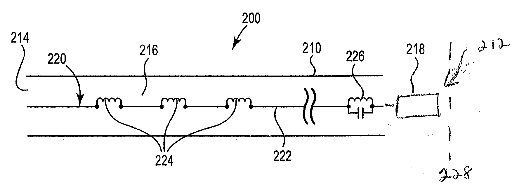
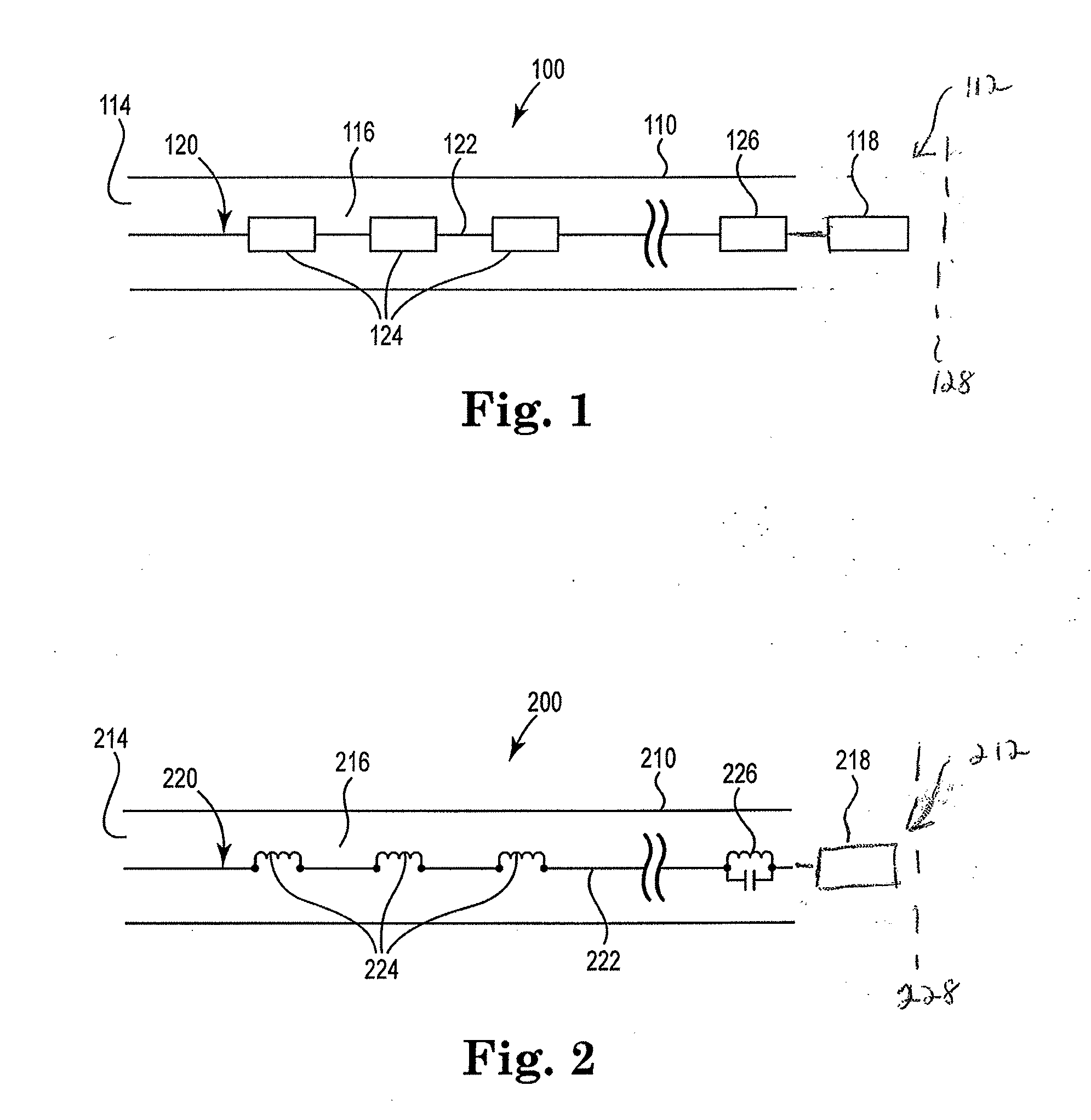
[0048]FIG. 1 is a block diagram illustrating the cable construct 100 in its simplest form in accordance with the present invention. Cable 100 broadly includes elongate body 110 having first 112 and second 114 ends and defining a lumen 116 therewithin. Lumen 116 houses circuit 120. Circuit 120 includes at least one wire 122 ...


PUM


Abstract

An MRI compatible cable construct is provided. The cable is adapted to be used with a medical device in direct electrical contact with a patient. Each cable or cable set includes a plurality of filter components. The filter component comprises at least two filter components. One filter component may be a resonant filter at a distal end that resolves the issue of insufficient attenuation by effectively blocking the RF induced current on the cable from exiting the cable at the distal. The second filter component may comprise one or more non-resonant filter(s) or inductors positioned along the length of the cable that resolve(s) the issue of excessive heating of the resonant LC filter by significantly attenuating the current induced on the cable before it reaches the resonant LC filter.

Description

RELATED APPLICATION DATA[0001]This application is a non-provisional of U.S. application Ser. No. 61 / 660,085, filed on Jun. 15, 2012, and is a continuation-in-part to U.S. application Ser. No. 12 / 743,954, filed May 20, 2010, which claims priority to International application Serial No.: PCT / US2010 / 026232, filed on Mar. 4, 2010, which also claims priority U.S. provisional application Ser. No. 61 / 157,482, filed on Mar. 4, 2009, the entireties of which are incorporated herein by reference.BACKGROUND OF THE INVENTION[0002]1. Field of the Invention[0003]The invention relates to medical devices used in the magnetic resonance imaging (MRI) environment and in particular to a conductive cable that may be used to connect medical devices and other peripheral equipment to a patient.[0004]2. Background of the Related Art[0005]MRI has achieved prominence as a diagnostic imaging modality, and increasingly as an interventional imaging modality. The primary benefits of MRI over other imaging modaliti...

Claims


Application Information

Patent Timeline
IPC IPC(8): H03H1/00
CPCA61B5/0422A61B5/055H03H1/0007A61B2017/00911A61N2001/086A61B18/1492A61N1/086A61B5/287
Inventor LLOYD, THOMAS W.WEDAN, STEVEN R.STENZEL, GREGG S.
Owner IMRICOR MEDICAL SYST
Why Eureka
Try Eureka