Methods for implanting a stent using a guide catheter

Inactive Publication Date: 2011-02-24
ABBOTT CARDIOVASCULAR
View PDF5 Cites 5 Cited by
  • Summary
  • Abstract
  • Description
  • Claims
  • Application Information

AI Technical Summary

Benefits of technology

[0007]The present invention is generally directed to methods for implanting a stent into an ostium or a proximal portion of a body vessel utilizing a guide catheter, rather than a conventional balloon angioplasty catheter, as the primary delivery device. By using the guide catheter as the primary stent delivery catheter, the guide catheter can function both as a conventional guide catheter to allow interventional instruments to be advanced therethrough and as a stent delivery catheter to simultaneously implant a stent in a location of the body vessel which is often difficult to implant a stent with conventional stent delivery devices. The present invention is particularly useful in allowing a physician to accurately implant a stent near the ostium of a main coronary artery branching from the aorta, while still achieving adequate guide catheter support for advancement of secondary treatment devices into the main coronary artery.
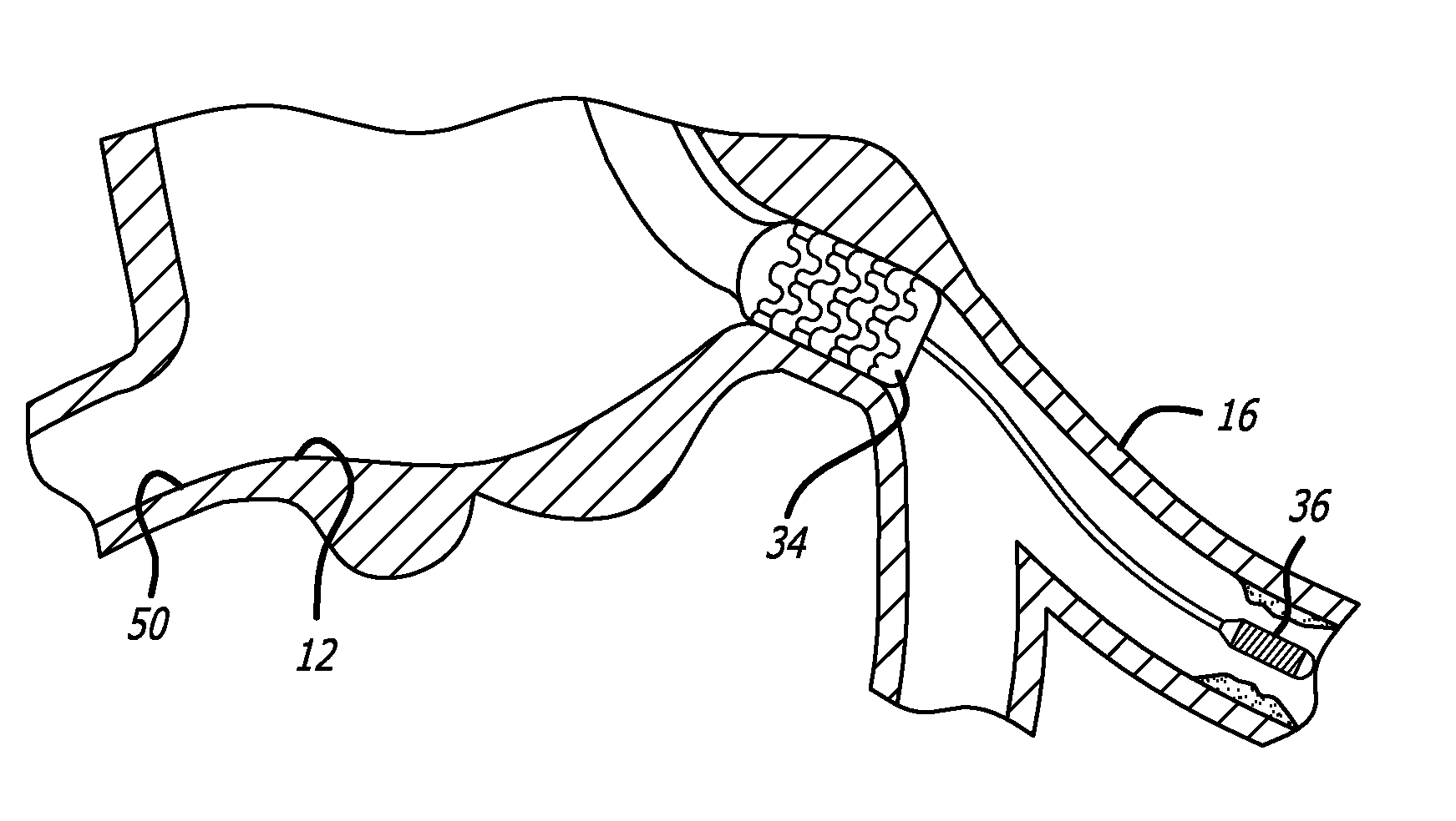
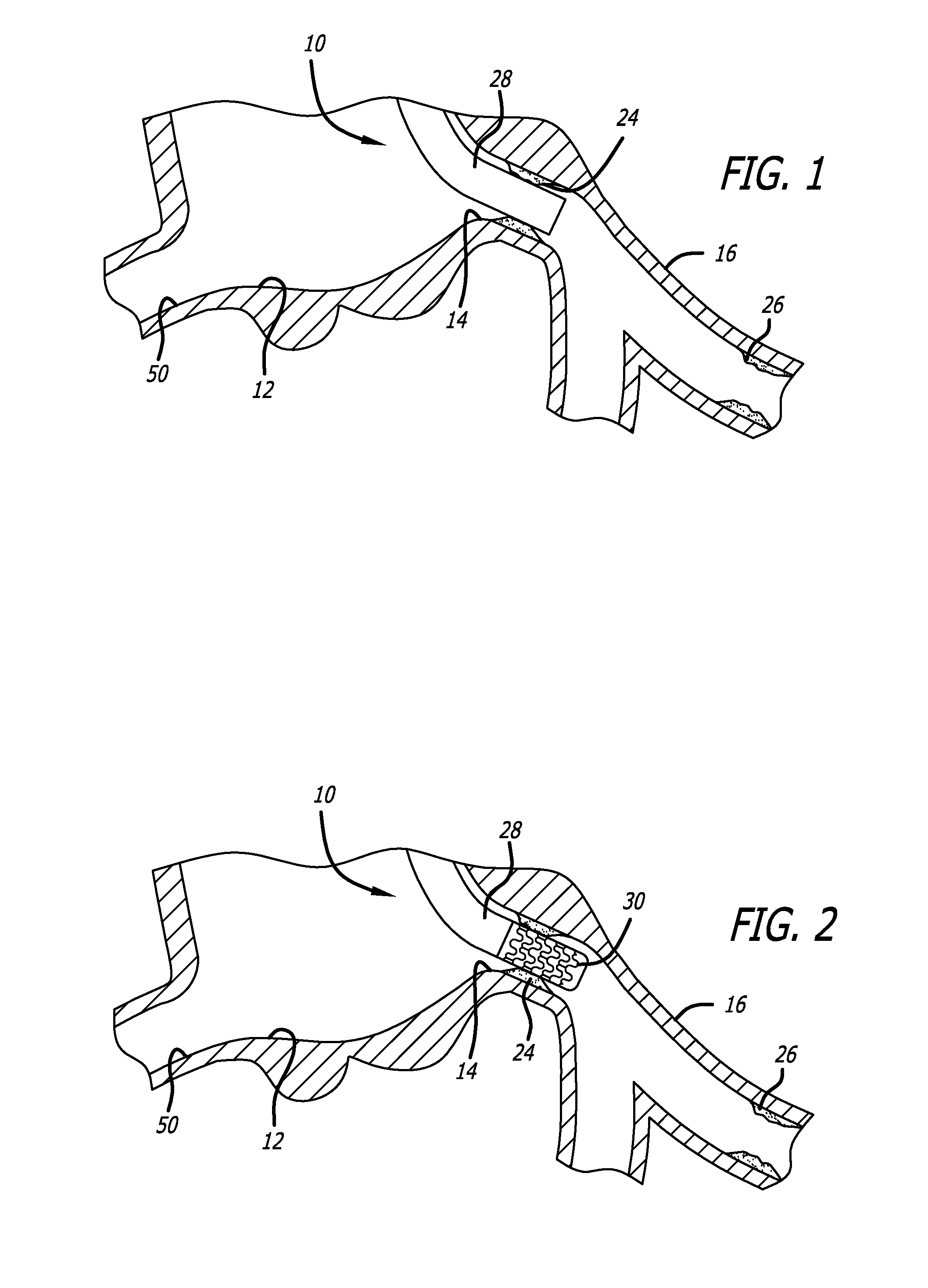
[0008]The methods of the present invention can utilize a guide catheter which includes a mounting region located at its distal end section upon which a stent can be mounted. Suitable stents which can be placed on the mounting region include, but are not limited to, balloon-expandable stents, self-expanding stent, bio-absorbable stents, drug-eluting stents and composite stents. When a 
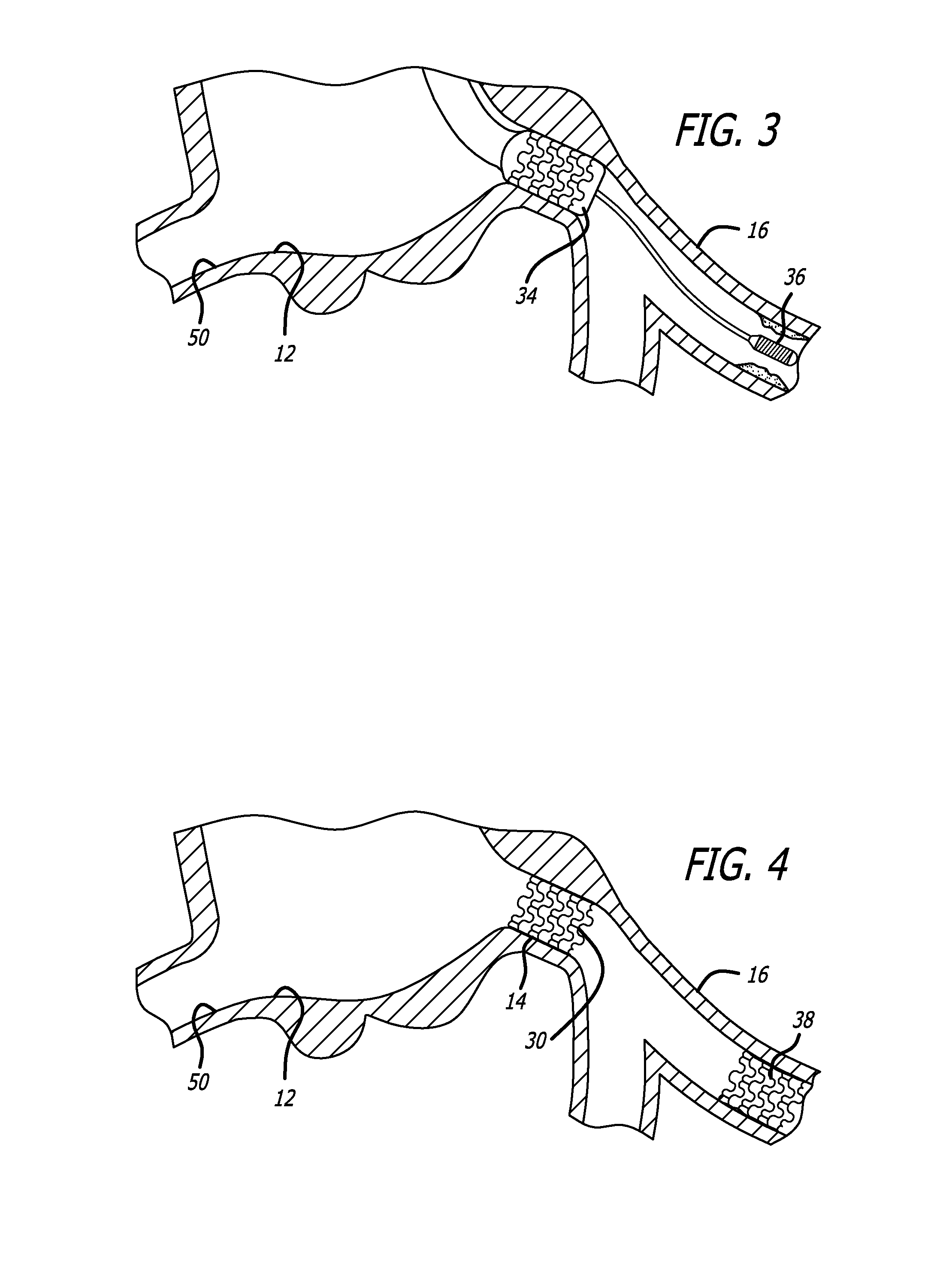
balloon expandable stent is to be implanted, the guide catheter should include an expandable member, such as a balloon, which is adapted to apply an outward radial force which expands the stent into the body lumen. The guide catheter would require a mechanism, such as an inflation lumen and an inflation port, which would be used to inflate the balloon. When a self-expanding stent is to be implanted, usually a retractable sheath would be co-axially disposed over the guide catheter to maintain the self-expanding stent in a collapsed, delivery position. The retractable sheath could be simply retracted to remove the restraint placed on the self-expanding stent, thus allowing the self-expanding stent to radially expand to its expanded position. A retractable sheath also could be used to cover a balloon-expandable, bio-absorbable and drug eluting stents to protect these stents as the guide catheter is being advanced into the patient's vasculature. As a result of using a protective outer sheath, there may be no need to crimp the stent onto the guide catheter, which would be beneficial especially if the stent has a fragile structure or is coated with a drug. The guide catheter can be made similar to conventional devices and include an elongated shaft with a preshaped or shapeable distal shaft section to facilitate placement of the distal tip of the guide catheter into a patient's body lumen.
[0010]In a further method of use, an interventional device can be advanced through the lumen of the guide catheter after the stent is implanted. As mentioned above, the guide catheter may include an expandable member upon which the stent is mounted. In using such a guide catheter, the method can include actuating the expandable member to implant the stent in the opening of the branch vessel, which will also help in anchoring the distal section of the guide catheter within the branch vessel. The expandable member can be, for example, an inflatable stent balloon. After the expandable member has been actuated, an additional interventional procedure(s) can be performed on one or more stenoses, lesions or damaged vessel located distal to the ostium by simply using the guide catheter to advance the necessary interventional devices through the lumen of the guide catheter. As a result of this method, the physician does not have to utilize a conventional stent delivery catheter to stent the sometimes difficult to stent ostium of the branch vessel.
[0011]As mentioned above, the stent can be covered during the time that the guide catheter is being advanced through the patient's vasculature. The method contemplates retracting the sheath in order to implant the stent. When the stent is a self-expanding type, the simple retraction of the sheath should allow the stent to self-expand to its expanded position. If the stent is a balloon expandable type, the sheath should first be retracted, otherwise the expansion of the balloon could cause the sheath to expand with the stent. Thereafter, the expandable member can be actuated to implant the stent at the area of stenosis in the ostium of the branch vessel. In one particular method of the present invention, the sheath can be made from a bio-absorbable material which starts to dissolve once making contact with the body fluid. In such a method, the sheath does not have to be retracted since the sheath will dissolve in time to expose the stent for implantation.

Problems solved by technology

Unfortunately, the anatomy of the main coronary arteries, particularly the left main coronary artery, can be relatively short and can compromise the support provided by the guiding catheter.
As the term implies, the guide catheter will move or back out of the ostium, which is detrimental to its function.
As a result, it can be difficult to place a stent in the region where the distal end of the guide catheter is seated, and if the guide catheter is not properly seated, it can back out.

Method used


Image

  • Methods for implanting a stent using a guide catheter
  • Methods for implanting a stent using a guide catheter
  • Methods for implanting a stent using a guide catheter

Examples


Embodiment Construction

[0023]Referring initially to FIGS. 1-4, a guide catheter 10 is depicted as it is being place in a patient's vasculature to implant a stent into an ostium of a body vessel extending from a main body vessel. For example, the guide catheter 10 can be advanced through the femoral artery to the aorta 12 for implanting a stent in the opening, or ostium 14, of the left main coronary artery 16. FIG. 5 illustrates one specific embodiment of a guide catheter 10 which can be used to implant the stent using the methods of the present invention. FIG. 5 shows the guide catheter 10 including a generally elongated catheter shaft 18 with a proximal section 20 and a distal section 22. In FIGS. 1-3, only the distal section 22 of the guide catheter 10 is shown being placed in the patient's vasculature. It should be appreciated that the proximal section 20 extends out of the patient to allow the physician to advance conventional interventional instruments into the left main coronary artery 16.

[0024]The ...


PUM


Abstract

Various methods for implanting a stent into an ostium or a proximal portion of a body vessel utilizing a guide catheter, rather than a convention balloon angioplasty balloon catheter, as the primary delivery device are disclosed. The guide catheter can be used as the primary stent delivery catheter for the ostium region of the body vessel and can be anchored to the vessel to allow secondary treatment devices to be advanced to distal locations in the body vessel.

Description

BACKGROUND OF THE INVENTION[0001]The invention relates to the field of intraluminal catheters, and particularly, to guiding catheters suitable for intravascular procedures such as angioplasty, stent deployment and the like.[0002]In percutaneous transluminal coronary angioplasty (PTCA) procedures, a catheter system is introduced into a patient's vasculature to open up a body lumen, usually a coronary artery, which has become partially blocked by a stenotic lesion. These procedures can also be used to open up other arteries which have become partially blocked, including, but not limited to the carotid arteries and peripheral arteries. The catheter system is usually inserted into the heart to treat a coronary artery by advancing the system through the femoral artery, although it is possible to access the coronary arteries through other arteries in the patient's vasculature.[0003]The catheter system usually includes a guide catheter, often referred to as a guiding catheter, which is use...

Claims


Application Information

Patent Timeline
IPC IPC(8): A61F2/84A61F2/82
CPCA61F2/958A61F2/966A61F2002/9583A61F2002/821A61F2/97
Inventor COFFEY, LORCAN J.TA, DIEM U.VON OEPEN, RANDOLFEL-NOUNOU, FOZAN O.KALVASS, LAURA M.
Owner ABBOTT CARDIOVASCULAR
Why Eureka
Try Eureka