Emergency braking system for machine tools

a technology of emergency braking and machine tools, applied in the field of protection systems, can solve the problems of corresponding time expenditure for procurement and installation, action on machining tools, and significant consequential costs

Active Publication Date: 2011-03-03
ROBERT BOSCH GMBH
View PDF7 Cites 31 Cited by
  • Summary
  • Abstract
  • Description
  • Claims
  • Application Information

AI Technical Summary

Benefits of technology

[0009]It is an object of the present invention to provide a protective system of a machine tool, in particular a reversible protective system, having a design which reliably triggers and develops its protective effect within a few milliseconds.

Problems solved by technology

A disadvantage is the direct action on the machining tool, i.e., on the cutting geometry of the saw blade, since additional hazard potential for the operator results when parts of the toothing break off.
This entails significant consequential costs and a corresponding time expenditure for the procurement and installation.
In addition, it may be assumed that all components affected by the braking operation, i.e., all revolving geometries of the machine tool, are subjected to severe stresses during the deceleration phase.
Neither the manufacturer nor applicable publications pertaining to this system provide data concerning the fatigue strength of the unit.
A disadvantage of this type of protective system is the necessity of moving relatively large masses, in the form of the systems to be lowered, under severe time constraints in the millisecond range.
The pyrotechnic ignition devices necessary for this purpose, which have proven to be indispensable for this protective actuator system, also result in costly partial reversibility, which limits immediate resumption of operations of the machine tool including a protective system which is ready for use, and also imposes time-related and organizational constraints.
In addition, due to space limitations and a very specific operating procedure, this protective system is suitable only for fairly large stationary equipment, for example circular table saws, which allow such a design in their interior.
However, as described in the cited publication, the disadvantage of this protective system is that subsequent to the triggering of the protective actuator system it is necessary to replace the complete brake unit due to the wedge which gets jammed in the friction pairing.
Thus, here as well, there is partial limitation of the immediate system reversibility.

Method used


Image

  • Emergency braking system for machine tools
  • Emergency braking system for machine tools
  • Emergency braking system for machine tools

Examples


Embodiment Construction

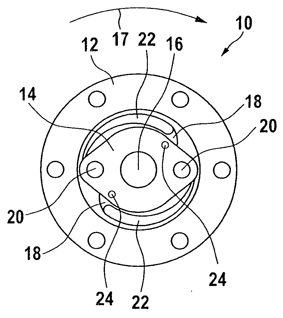
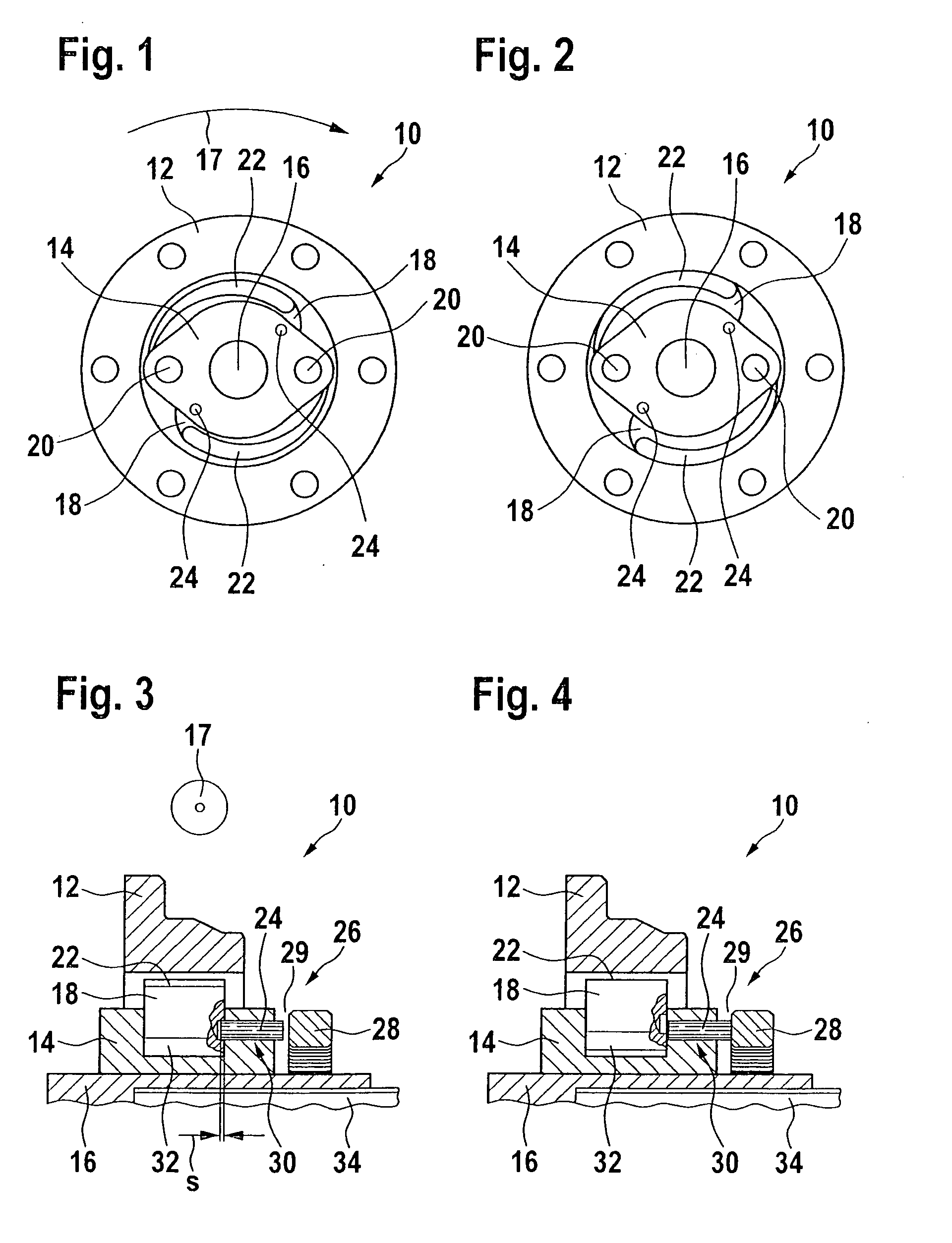
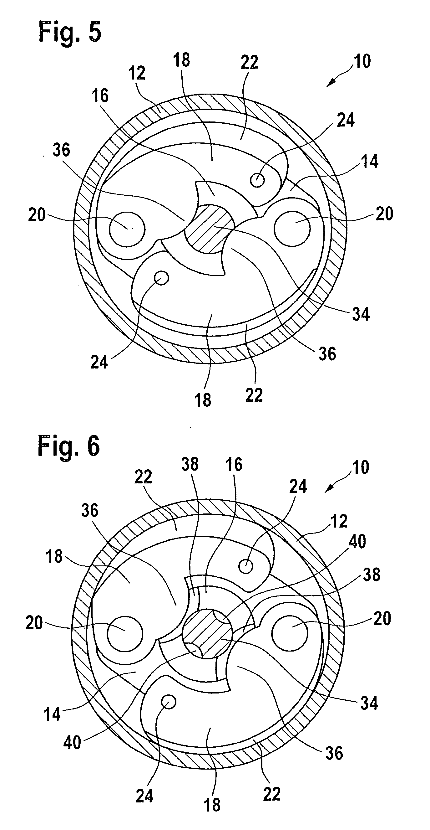
[0046]The design principle of the emergency braking system according to the present invention is explained with reference to FIGS. 1 through 6. FIGS. 7, 8, and 9 are used to describe details of the actuator for the locking device of the braking system according to the present invention, the diagnostic system, and the interaction of these two units. FIGS. 10 and 11 show a machine tool according to the present invention in the form of a circular table saw having an emergency braking system according to the present invention.

[0047]FIGS. 1 through 6 show schematic views of an emergency braking system according to one example embodiment of the present invention, which is denoted overall by reference numeral 10 and which is used, for example, to bring a saw blade of a circular table saw (not shown here; see FIG. 10) which is in a hazardous situation to a standstill within a very short time period in the range of a few milliseconds.

[0048]Emergency braking system 10 for a machine tool for a...


PUM

PropertyMeasurementUnit
timeaaaaaaaaaa
currentaaaaaaaaaa
time-resolved characteristic curveaaaaaaaaaa

Abstract

An emergency braking system for a machine tool for abruptly braking a revolving shaft includes at least one brake drum and at least one brake shoe which are engaged with one another in order to brake the shaft. The braking intervention between the brake drum and the brake shoe takes place under the influence of a centrifugal force resulting from the rotation of a shaft as soon as a locking device is released. Also provided in the braking system is a diagnostic system which allows the functionality of the locking device to be checked.

Description

BACKGROUND OF THE INVENTION[0001]1. Field of the Invention[0002]The present invention relates to a protective system, in particular an emergency braking system for a machine tool, e.g., a circular saw, which develops its protective effect within a very short time period which is generally in the range of several milliseconds (typically 1 to 50 ms) in order to protect a user of the machine tool from injuries in hazardous situations.[0003]2. Description of Related Art[0004]At the present time there are essentially three different approaches for implementing such a protective system for table and format circular saws, which are intended to prevent a user from coming into contact with the revolving saw blade or incurring a serious cut injury.[0005]The protective system of a U.S. manufacturer, provided and marketed under the company name SawStop Inc., is an emergency braking system which allows the machine tool to be braked as the result of a direct intervention in the saw blade by a bra...

Claims


Application Information

Patent Timeline
Patent Type & Authority Applications(United States)
IPC IPC(8): B27G19/02F16D51/00F16D51/16F16D65/27B26D7/24F16D65/22
CPCB23Q11/0092B23Q17/00F16D51/26F16P3/147F16D2127/002F16P3/14F16D2121/20B27G19/02Y10T83/081
Inventor WINKLER, THOMAS
Owner ROBERT BOSCH GMBH
Why Eureka
Try Eureka