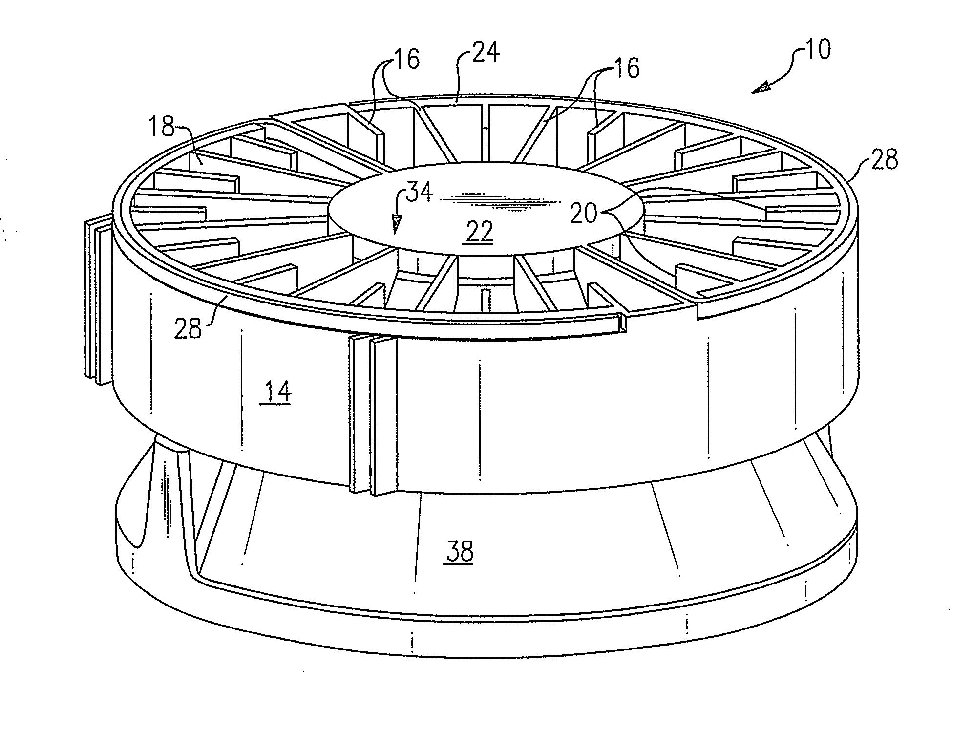
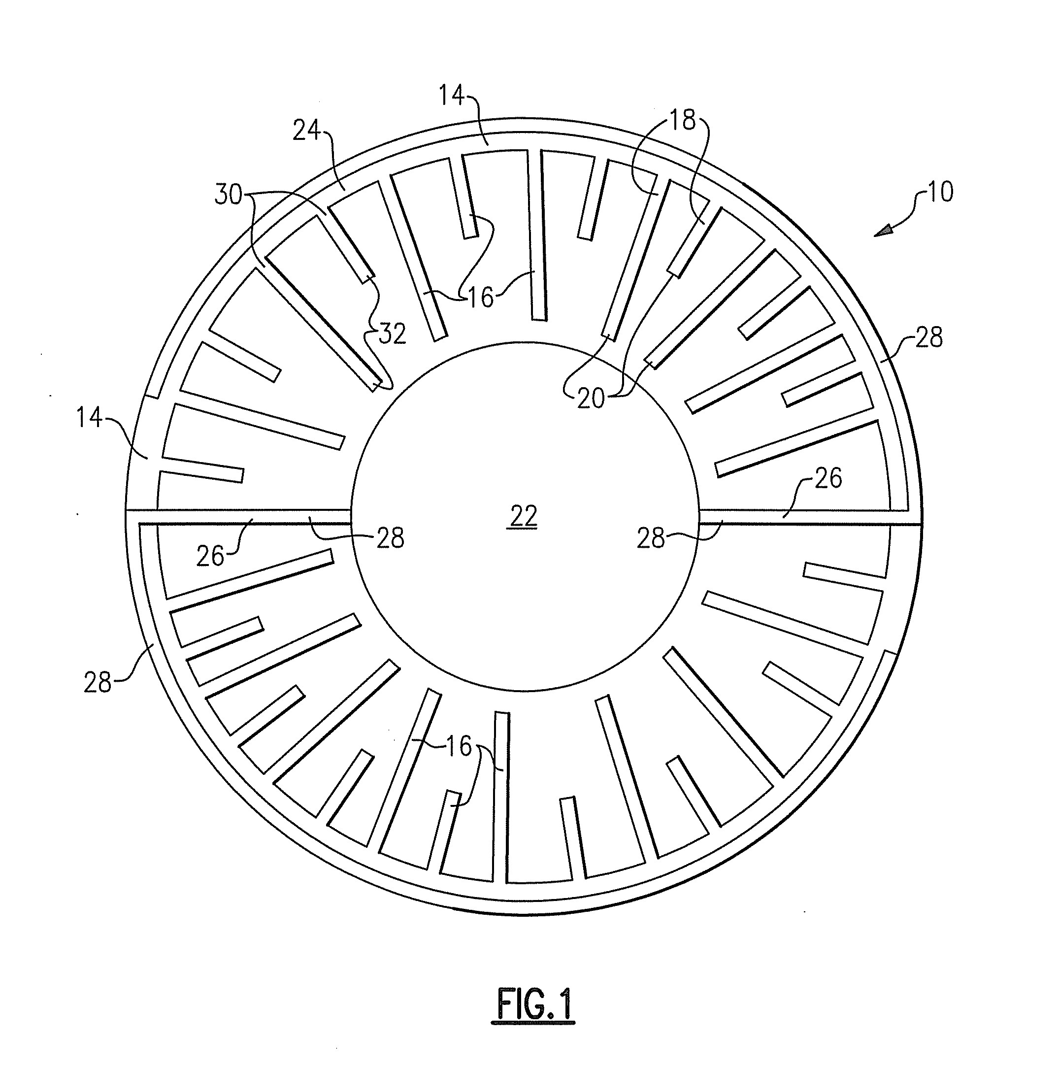
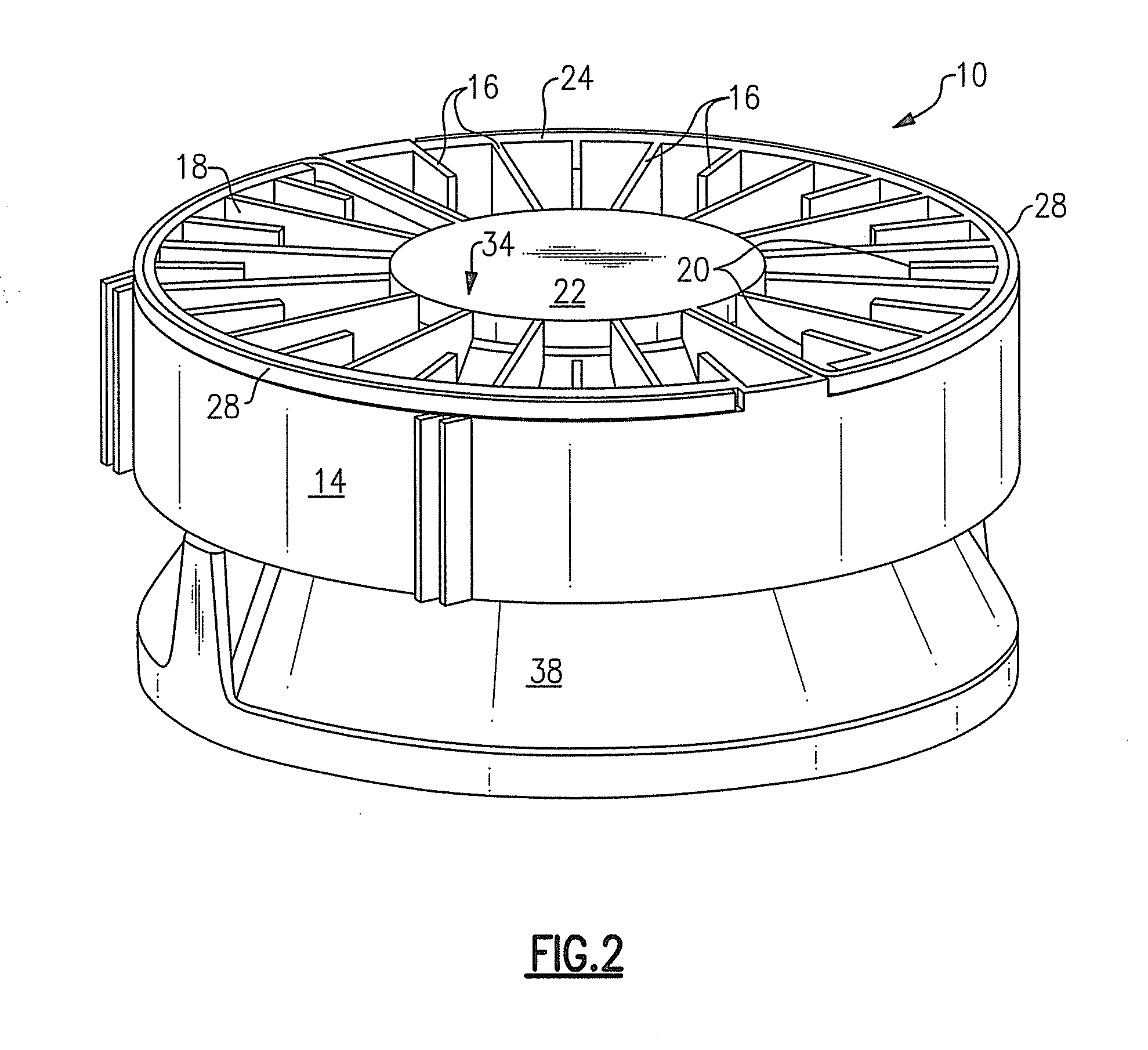
Lighting device with heat dissipation elements

a technology heat dissipation elements, which is applied in the direction of discharge tube main electrodes, semiconductor devices for light sources, lighting and heating apparatus, etc., can solve the problems of incandescent bulbs and other light sources producing a great deal of heat, and achieves simple and effective, low thermal resistance, and long life of light emitting diodes

Active Publication Date: 2011-03-03
IDEAL IND LIGHTING LLC
View PDF103 Cites 71 Cited by
  • Summary
  • Abstract
  • Description
  • Claims
  • Application Information

AI Technical Summary

Benefits of technology

[0012]In many instances where lighting devices include solid state light emitters as light sources (e.g., general illumination devices which emit white light in which the light sources consist of light emitting diodes), a plurality of solid state light emitters are provided which emit light of different colors which, when mixed, are perceived as the desired color for the output light (e.g., white or near-white). As noted above, the intensity of light emitted by many solid state light emitters, when supplied with a given current, can vary as a result of temperature change. The desire to maintain a relatively stable color of light output is therefore an important reason to try to reduce temperature variation of solid state light emitters.
[0013]In addition, the potential for variation in intensity of solid state light emitters (e.g., depending on the ambient temperature and / or the age of the solid state light emitter) has in many instances led to the inclusion in some lighting devices which include solid state light emitter of one or more sensors which detect (1) the color of the light being emitted from the lighting device, and / or (2) the intensity of the light being emitted from one or more of the solid state light emitters, and / or (3) the intensity of light of one or more specific hues of color. By providing such sensors, it is possible to adjust the current supplied to one or more of the solid state light emitters, based on the readings from such sensor(s), in order to maintain the color of the output light within a desired range of color.
[0014]With lighting devices that include light emitting diodes, the lower the thermal resistance from the light emitting diode to the environment, the greater light that can be generated from a lighting device without exceeding the optimum maximum junction temperature (or, similar amounts of light can be generated with a lower light emitting diode junction temperature, possibly enabling longer light emitting diode life). Typical passive thermal solutions, such as extruded or cast heat sinks, are simple and effective, but use a significant amount of material in order to conduct the required amount of heat away from the lighting device.
[0027]In some embodiments, the lighting devices according to the present inventive subject matter can allow for minimal material height above the plane of the light emitters) (and / or above the plane of a circuit board, e.g., a circuit board on which light emitting diodes are mounted), can allow for significantly reduced material usage, can significantly increase the effectiveness of surface area exposed to the environment, can utilize space that would otherwise be “dead space” in the design for thermal management, can allow for easy handling by an installer, and / or can provide a clean and / or aesthetically appealing appearance.

Problems solved by technology

Incandescent bulbs and other light sources produce a great deal of heat when in use.

Method used


Image

  • Lighting device with heat dissipation elements
  • Lighting device with heat dissipation elements
  • Lighting device with heat dissipation elements

Examples


Embodiment Construction

[0036]The present inventive subject matter now will be described more fully hereinafter with reference to the accompanying drawings, in which embodiments of the inventive subject matter are shown. However, this inventive subject matter should not be construed as limited to the embodiments set forth herein. Rather, these embodiments are provided so that this disclosure will be thorough and complete, and will fully convey the scope of the inventive subject matter to those skilled in the art. Like numbers refer to like elements throughout. As used herein the term “and / or” includes any and all combinations of one or more of the associated listed items. All numerical quantities described herein are approximate and should not be deemed to be exact unless so stated.

[0037]The terminology used herein is for the purpose of describing particular embodiments only and is not intended to be limiting of the inventive subject matter. As used herein, the singular forms “a”, “an” and “the” are intend...


PUM


Abstract

A lighting device comprising at least a first light emitter, at least a first heat transfer element, and a plurality of heat dissipation elements. Each heat dissipation element has at least a first region and a second region, the first region being in contact with the first heat transfer element, the second region being closer to the first light emitter than the first region. The first light emitter is thermally coupled to the first heat transfer element.

Description

FIELD OF THE INVENTIVE SUBJECT MATTER[0001]The present inventive subject matter is directed to a lighting device, in particular to a lighting device with heat dissipation elements.BACKGROUND[0002]There is an ongoing effort to develop systems that are more energy-efficient. A large proportion (some estimates are as high as twenty-five percent) of the electricity generated in the United States each year goes to lighting. Accordingly, there is an ongoing need to provide lighting which is more energy-efficient.[0003]Persons of skill in the art are familiar with a variety of types of light emitters for use in lighting devices.[0004]It is well known that incandescent light bulbs are very energy-inefficient light sources—about ninety percent of the electricity they consume is released as heat rather than light. Fluorescent light bulbs are more efficient than incandescent light bulbs (by a factor of about 10) but are still less efficient than solid state light emitters, such as light emitti...

Claims


Application Information

Patent Timeline
Patent Type & Authority Applications(United States)
IPC IPC(8): H01J61/52
CPCF21V29/004F21V29/006F21Y2101/02F21Y2105/001F21V29/51F21V29/89F21V29/507F21V29/75F21V29/773F21V29/87F21V29/505F21Y2105/10F21Y2115/10
Inventor PICKARD, PAUL KENNETH
Owner IDEAL IND LIGHTING LLC
Why Eureka
Try Eureka