Sensor system for monitoring surroundings on a mechanical component and a method for activating and evaluating the sensor system

a sensor system and mechanical component technology, applied in the direction of resistance/reactance/impedence, force measurement, instruments, etc., can solve the problems of affecting the operation of the machine, etc., to achieve the effect of reducing the cos

Active Publication Date: 2011-03-03
ROBERT BOSCH GMBH
View PDF14 Cites 28 Cited by
  • Summary
  • Abstract
  • Description
  • Claims
  • Application Information

AI Technical Summary

Benefits of technology

[0012]An object of the present invention to make possible operator-safe cooperation of humans and moving machine parts in the same work space at the same time.
[0013]An example sensor system according to the present invention, with a modular structure, may be applied to moving machine parts at relatively little expense, so that an approach of humans and / or contact with humans is detected reliably and these events may be reported to electrical signal outputs. Reliable detection means in this case that a malfunction of a sensor element may also be diagnosed promptly without danger to the human. In particular, with the flexible layers according to the present invention, even complexly shaped surfaces on machines may be covered without gaps in a simple manner with this sensor system.

Problems solved by technology

With such automatic production or assembly machines, an encounter of humans such as operators or service personnel for the automatic production or assembly machines with moving machines or machine parts may result in collisions that endanger the human and / or the functioning of the machine.
On the other hand, with relatively complexly shaped surfaces or a complex path motion of the dangerous machine part, consistent monitoring of the surroundings with the aid of sensors is often possible only using very great effort, or perhaps not even at all.
For example, optical detection may be impeded at edges and undercuts of the machine surface by shading, or integration of sensors may fail due to lack of installation space.
Such applications require duplicate and independently executed monitoring by sensors.
It is no longer possible to work directly together on an automatic production or assembly machine using such a protective fence, however, since the human and the machine cannot use the same work space at the same time here.
For example, the human and the machine cannot perform joint operating procedures.
Mounting such a structure on different industrial robots is often complicated and expensive, however.

Method used


Image

  • Sensor system for monitoring surroundings on a mechanical component and a method for activating and evaluating the sensor system
  • Sensor system for monitoring surroundings on a mechanical component and a method for activating and evaluating the sensor system
  • Sensor system for monitoring surroundings on a mechanical component and a method for activating and evaluating the sensor system

Examples


Embodiment Construction

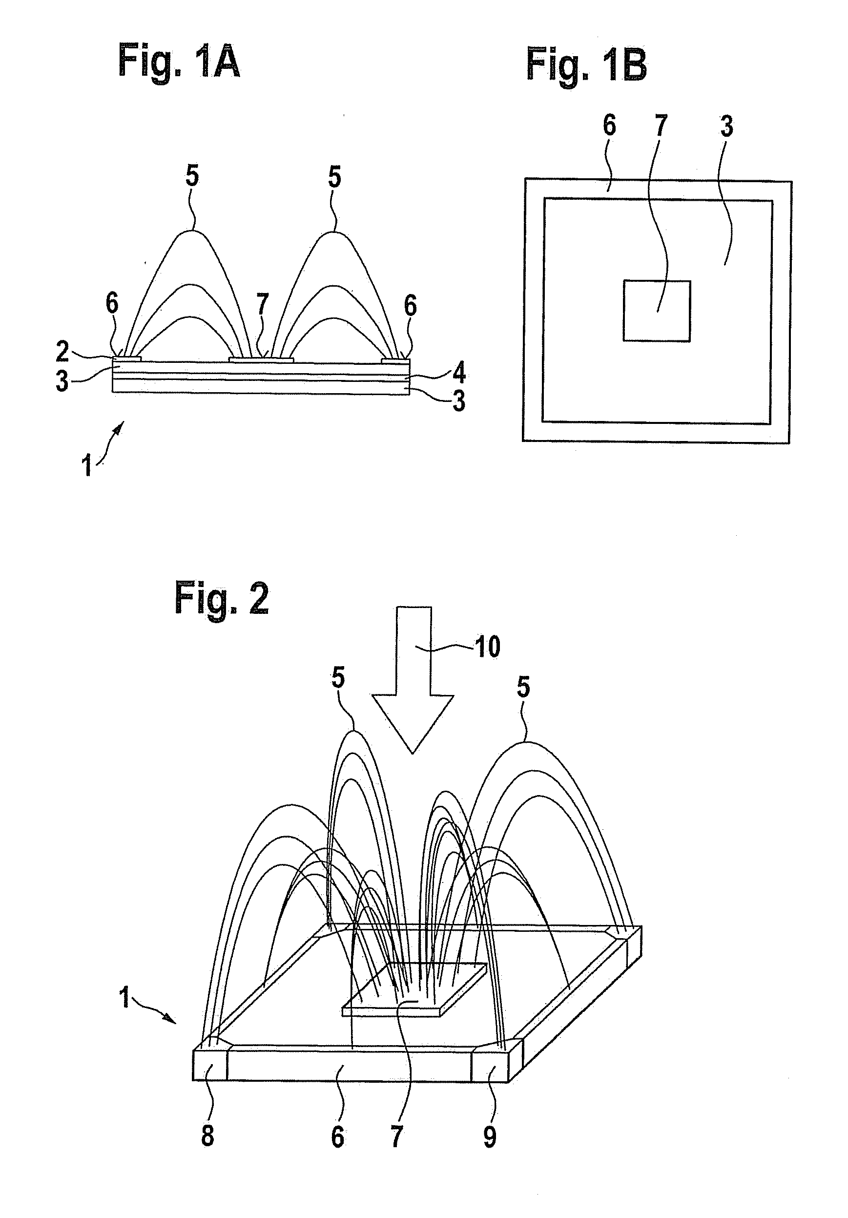
[0050]FIG. 1A shows a schematic view of a capacitive sensor element 1 of layered assembly, which includes a flexible, for example, textile-like electrically conductive layer 2 (for example, Cu matting), an electrically insulating, for example, likewise textile-like layer 3 (for example, mesh or sponge rubber), another electrically conductive layer as a shielding electrode 4 and another electrically insulating layer 3, which is mountable on a machine (not shown here), for example by bonding. Also recognizable are electrical field lines 5, which form between potential surfaces 6 and 7 of layer 2.

[0051]FIG. 1B shows a top view of surfaces 6 and 7 and insulating layer 3 in a square assembly. Here potential surface 6 represents a signal electrode and potential surface 7 the measuring electrode.

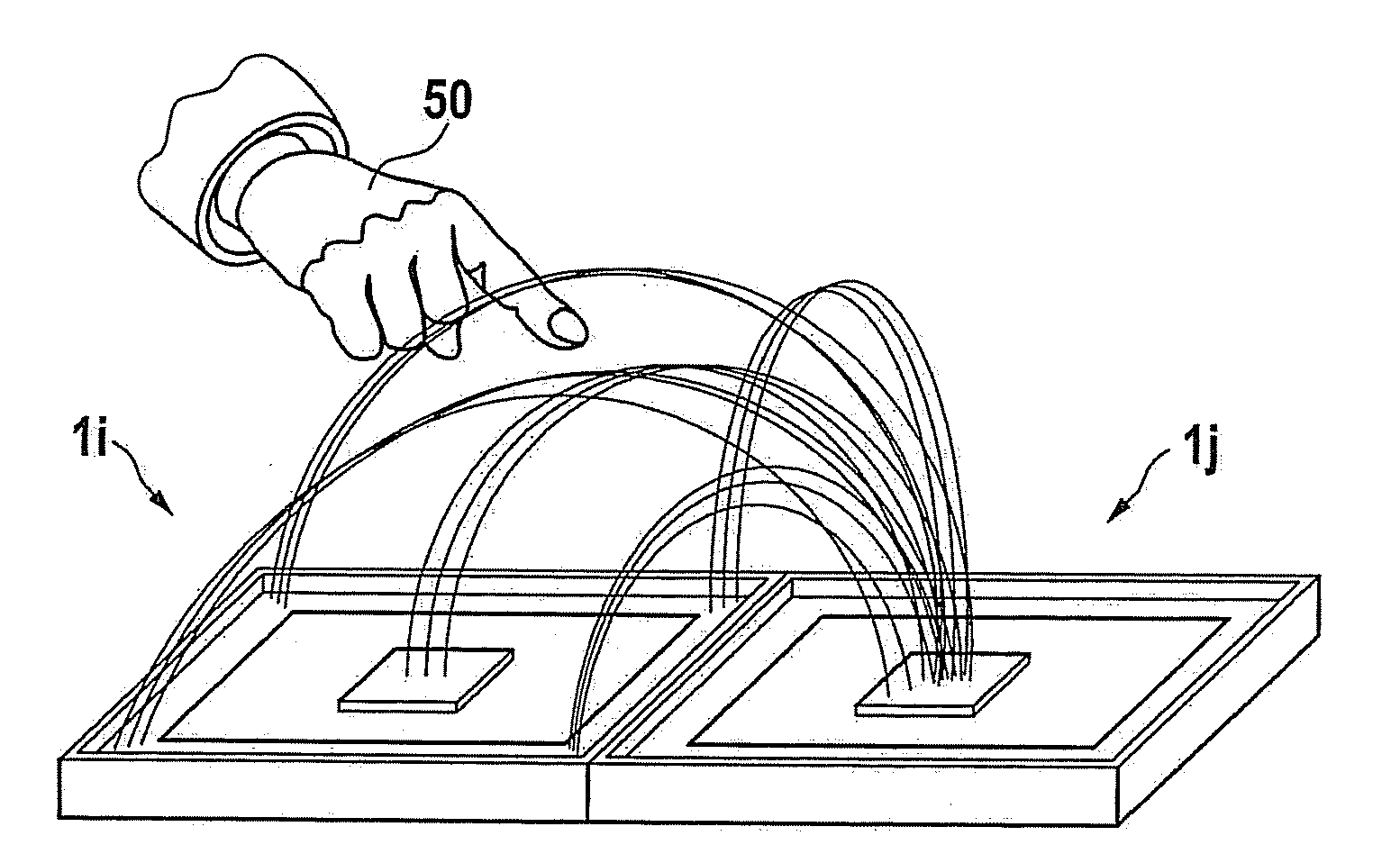
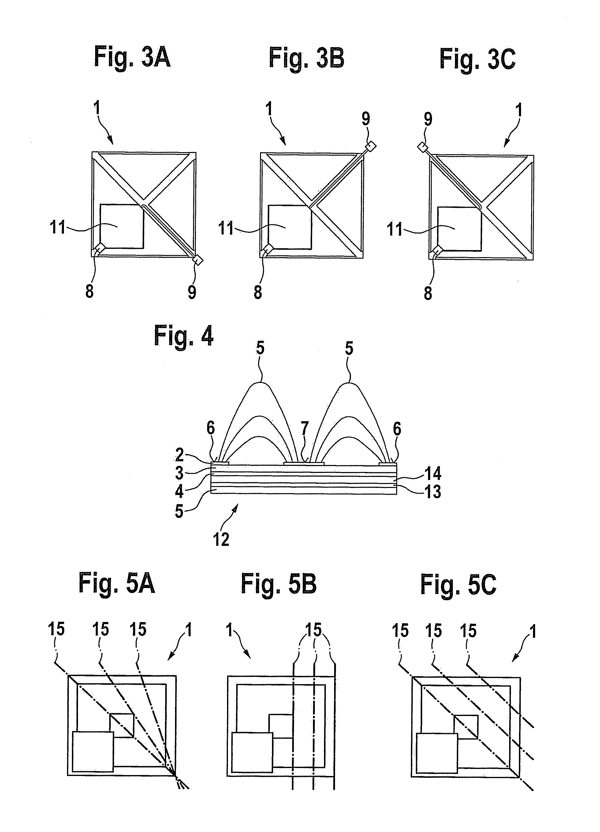
[0052]FIG. 2 shows sensor element 1 from FIGS. 1A, B in a different view, sockets 8 and plugs 9 for coupling additional sensor elements 1 also being indicated schematically. The capacitance between...


PUM


Abstract

A sensor system and an evaluation method for monitoring surroundings on a mechanical component, having at least one capacitive sensor element that is attachable on the surface of machines or machine parts, in which at least one sensor element is made up of a layered structure of flexible, electrically conductive and electrically insulating layers, electrically conductive surfaces of one layer being positioned with lateral spacing above insulating layers lying between them in such a way that electrical field lines form between the conductive surfaces, which change measurably upon approach to and/or contact with a body or object.

Description

CROSS REFERENCE[0001]The present application claims the benefit under 35 U.S.C. §119 of German Patent Application No. 102009029021.4 filed on Aug. 31, 2009, which is expressly incorporated herein by reference in its entirety.FIELD OF THE INVENTION[0002]The present invention relates to a sensor system for monitoring surroundings, in particular also for detecting collisions on a mechanical component, and a method for activating and evaluating the sensor system, in particular for monitoring approaches to a machine or to machine parts of automatic production or assembly machines.BACKGROUND INFORMATION[0003]With such automatic production or assembly machines, an encounter of humans such as operators or service personnel for the automatic production or assembly machines with moving machines or machine parts may result in collisions that endanger the human and / or the functioning of the machine. When such an approach is detected early, or even in the event of contact, measures may be taken ...

Claims


Application Information

Patent Timeline
Patent Type & Authority Applications(United States)
IPC IPC(8): G01R27/26
CPCF16P3/14F16P3/148G01L1/142G01D5/2405
Inventor FRANGEN, JOACHIM
Owner ROBERT BOSCH GMBH
Why Eureka
Try Eureka