
Optical sheet, backlight unit and liquid crystal display device having the same and method of fabricating optical sheet

a technology of optical sheet and backlight unit, which is applied in the direction of optical elements, lighting and heating apparatus, instruments, etc., can solve the problems of increasing the thickness of the backlight unit, preventing the implementation of a thin lcd device, and increasing the fabricating cost, so as to reduce the thickness of the lcd device and reduce the fabricating cost

Inactive Publication Date: 2011-03-03
LG DISPLAY CO LTD
View PDF10 Cites 20 Cited by
  • Summary
  • Abstract
  • Description
  • Claims
  • Application Information

AI Technical Summary

Benefits of technology

[0020]Therefore, to solve the problems of the related art, an object of the present invention is to provide a backlight unit capable of decreasing a fabricating cost and remarkably reducing a thickness of an LCD device by employing an optical sheet having prism patterns and refraction layers having a larger refractive index than that of the prism pattern, and an LCD device having the same.
[0025]In the present invention, light can be supplied almost perpendicular to a surface of the LC panel by virtue of a single optical sheet, resulting in remarkable decrease of the thickness of the LCD device and a fabrication cost thereof. Also, in the present invention, light can be supplied to the LC panel at an incident light angle of −10˜10° with respect to a normal of the LC panel (i.e., 80˜100° with respect to the surface of the LC panel), thus maximizing luminance, thereby implementing an image with high quality.

Problems solved by technology

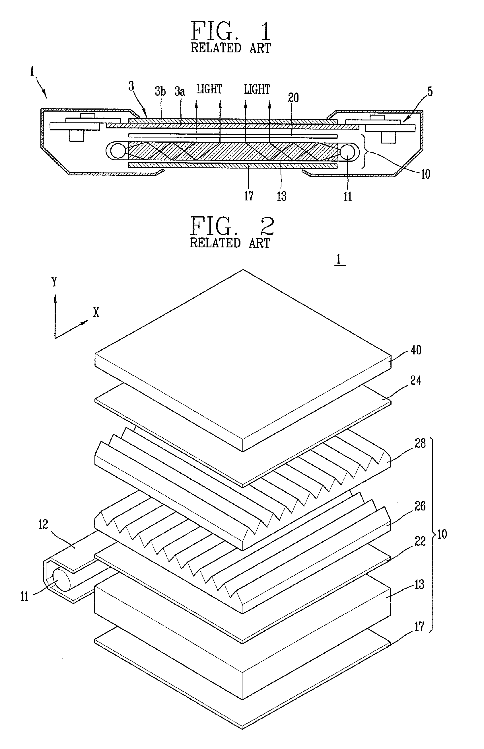
However, for the backlight unit in the structure, the optical sheet 20 is implemented by using the first and second diffusion sheets 22 and 24, and the first and second prism sheets 26 and 28, thereby increasing a fabricating cost.
Furthermore, the optical sheet 20 may cause the backlight unit to be thicker, which prevents an implementation of a thin LCD device.

Method used


Image

  • Optical sheet, backlight unit and liquid crystal display device having the same and method of fabricating optical sheet
  • Optical sheet, backlight unit and liquid crystal display device having the same and method of fabricating optical sheet
  • Optical sheet, backlight unit and liquid crystal display device having the same and method of fabricating optical sheet

Examples


Embodiment Construction

[0041]Hereinafter, a backlight unit for an LCD device in accordance with the present invention will be described with reference to the accompanying drawings.

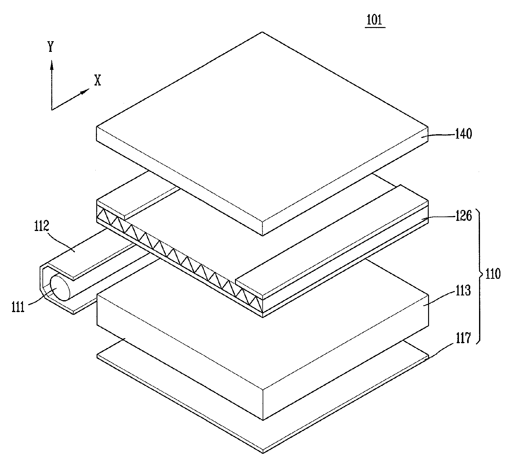
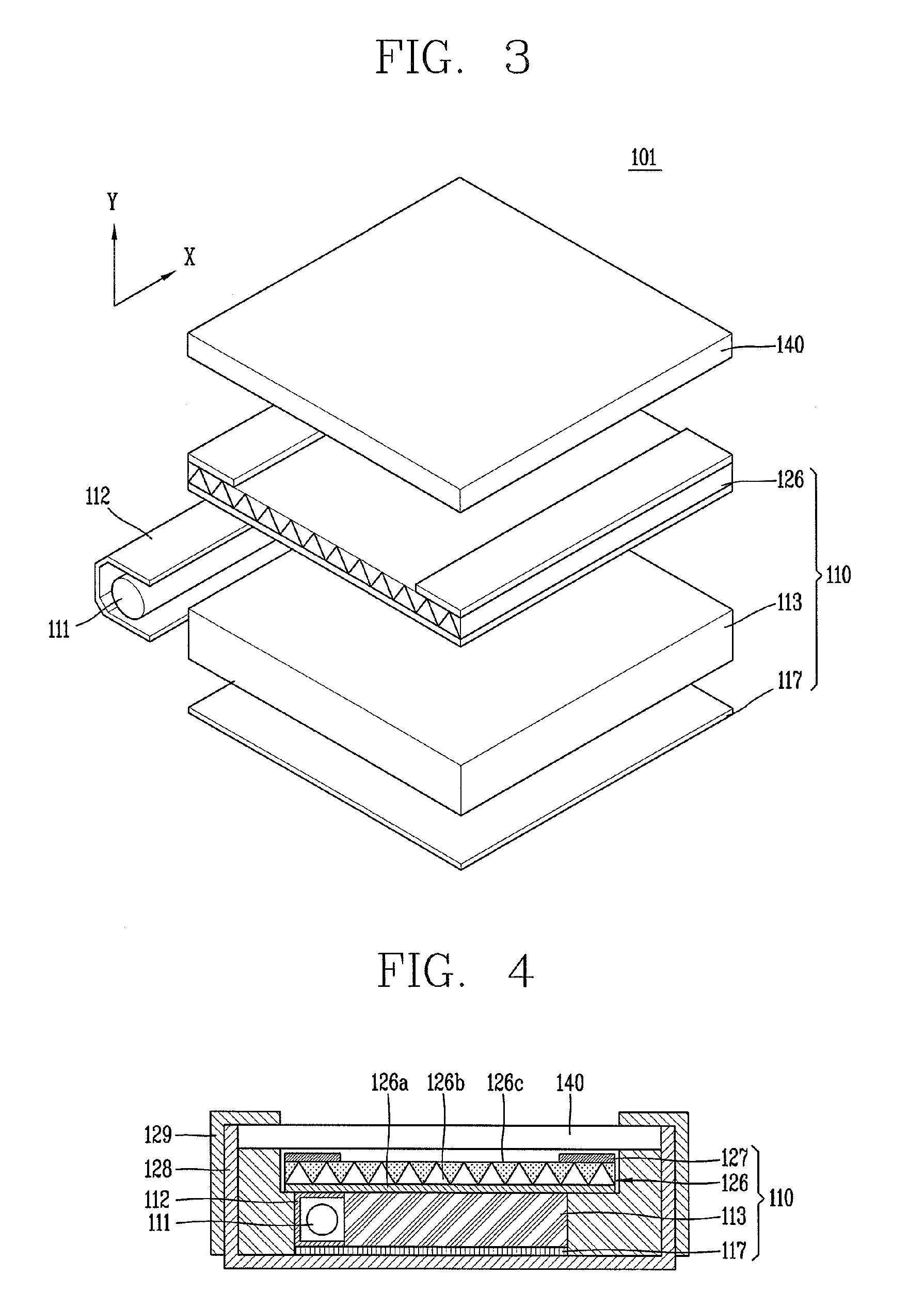
[0042]FIG. 3 is a view showing an LCD device 101 having a backlight unit 110 in accordance with the present invention.

[0043]As shown in FIG. 3, the LCD device 101 according to the present invention may include an LC panel 140 and a backlight unit 110. The backlight unit 110 may be present below the LC panel 140 so as to supply light to the LC panel 140.

[0044]The backlight unit 110 may include a light source 111 implemented as a lamp, a housing 112 for the light source 111, a light guide plate 113 disposed below the LC panel 140 to urge a side surface thereof contact the light source 111 so as to guide light input via the side surface thereof toward the LC panel 140, a reflector 117 disposed below the light guide plate 113 for reflecting light incident onto a lower side of the light guide plate 113 toward the LC panel 140, and an...


PUM

PropertyMeasurementUnit
incident light angleaaaaaaaaaa
refractive indexaaaaaaaaaa

Abstract

Disclosed is to decrease a fabrication cost and reduce a thickness of a liquid crystal display device by processing light transmitted through a liquid guide plate by virtue of a single optical sheet, the optical sheet including a base film, a plurality of prism patterns extending from one side to another side of the base film, and refraction layers between the prism patterns, thereby totally reflecting light incident from the light guide plate to be supplied to a liquid crystal display panel.

Description

[0001]Pursuant to 35 U.S.C. §119(a), this application claims the benefit of earlier filing date and right of priority to Korean Application No. 10-2009-0080644 filed on Aug. 28, 2009, the contents of which is incorporated by reference herein in its entirety.BACKGROUND OF THE INVENTION[0002]1. Field of the Invention[0003]The present invention relates to an optical sheet, backlight unit and a liquid crystal display device having the same.[0004]2. Background of the Invention[0005]Recently, the development of various types of portable electric equipment, such as mobile phones, personal digital assistants (PDAs), and note book computers, is increasing the demands on flat panel display devices which are applicable to those equipment and small in size, light in weight and power-efficient. Examples of the flat panel display device are a liquid crystal display (LCD) device, a plasma display panel (PDP) device, a field emission display (FED) device, a vacuum fluorescent display (VFD) device a...

Claims


Application Information

Patent Timeline
Patent Type & Authority Applications(United States)
IPC IPC(8): G02F1/13357F21V5/02B05D5/06
CPCG02B5/02G02B6/0053G02B6/0051G02B5/045G02B5/04G02F1/1335
Inventor KIM, SUNG-HUNKIM, BYOUNG-KUPARK, JAE-HYUNYOON, HYEOK-JOON
Owner LG DISPLAY CO LTD
Learn More