
Light source unit and projector

a technology of light source unit and projector, which is applied in the direction of instruments, lighting and heating apparatus, spectral modifiers, etc., can solve the problems of reduced light utilization efficiency of light emitted from the respective light emitting diodes, increased heat value and consumption power, and increased size of the main body of the projector, so as to achieve enhanced luminescence intensity, high luminance, and high intensity

Active Publication Date: 2011-03-03
CASIO COMPUTER CO LTD +1
View PDF2 Cites 76 Cited by
  • Summary
  • Abstract
  • Description
  • Claims
  • Application Information

AI Technical Summary

Benefits of technology

[0010]An object of the invention is to provide a light source unit which can emit light of high luminance and high intensity without increasing the quantity of excitation light by determining a concentration of weight content of a fluorescent material in a fluorescent material layer and a thickness of the fluorescent material layer so that luminescence intensity is enhanced when excitation light in a predetermined wavelength band is shone onto the fluorescent material layer in the way described above and a projector which includes the light source unit.
[0021]According to the invention, there can be provided provide the light source unit which can emit light of high luminance and high intensity without increasing the quantity of excitation light by determining the concentration of weight content of the fluorescent material in the fluorescent material layer and the thickness of the fluorescent material layer so that luminescence intensity is enhanced when excitation light in the predetermined wavelength band is shone onto the fluorescent material layer and the projector which enables a projection of high luminance and high lightness by including the light source unit described above.

Problems solved by technology

However, in the invention described in the patent document, the number of bright points of the light emitting devices is increased, and this causes a problem that the light utilization efficiency of light emitted from the respective light emitting diodes is reduced due to the Etendue value of the light source which is expressed by a product of light emitting area and solid angle becoming larger than the Etendue value of the display device which is expressed by a product of the area of the display device and solid angle.
However, using a plurality of excitation light sources to increase the quantity of excitation light leads to an increase in heat value and an increase in consumed power.
In addition, such an attempt also leads to an increase in size of a main body of a projector.

Method used


Image

  • Light source unit and projector
  • Light source unit and projector
  • Light source unit and projector

Examples


Embodiment Construction

[0031]Hereinafter, a preferred mode for carrying out the invention will be described by use of the accompanying drawings. Although various limitations which are technically preferable for carrying out the invention are imposed on an embodiment which will be described below, the scope of the invention is not limited in any way to the following description and illustrated examples.

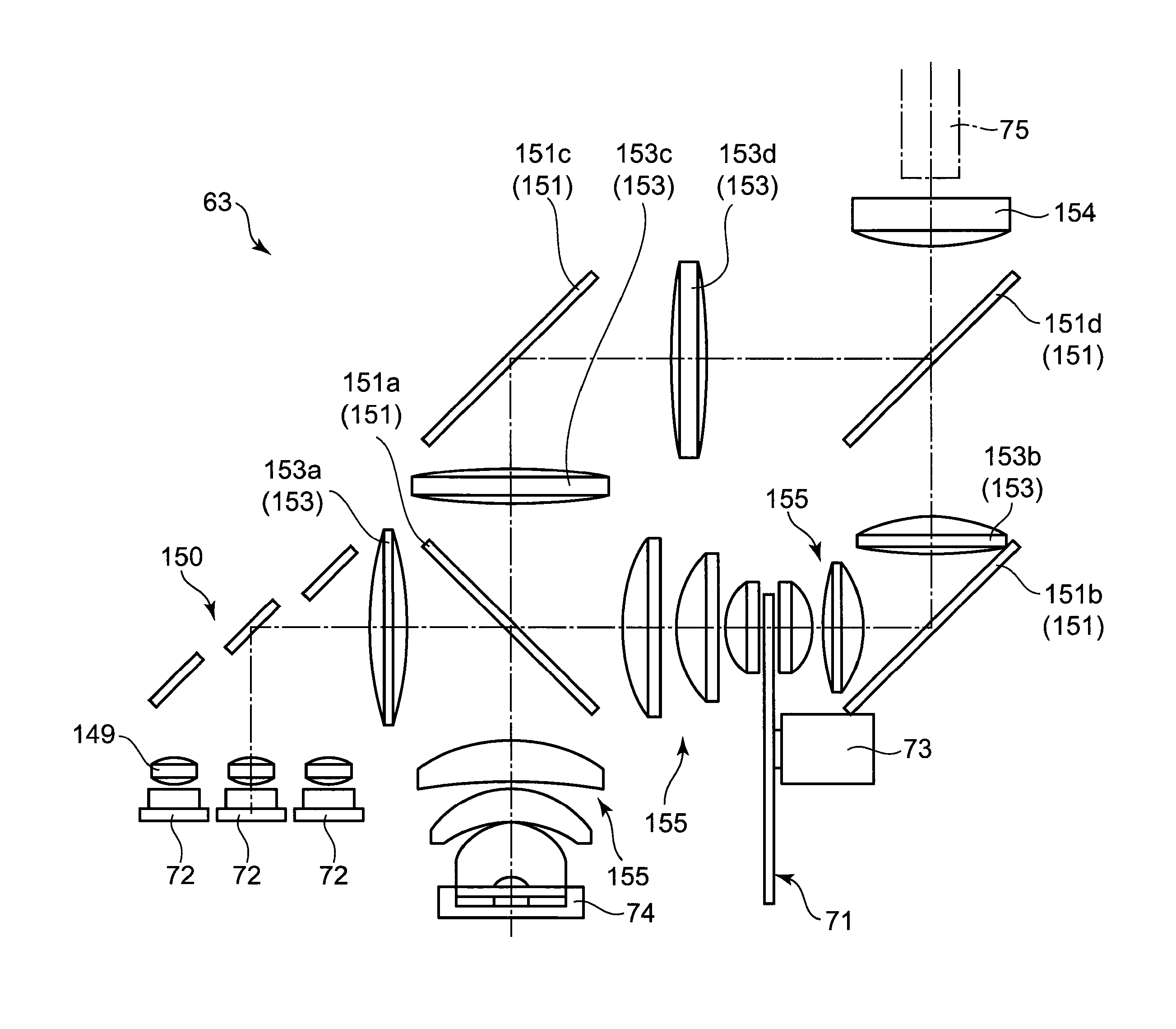
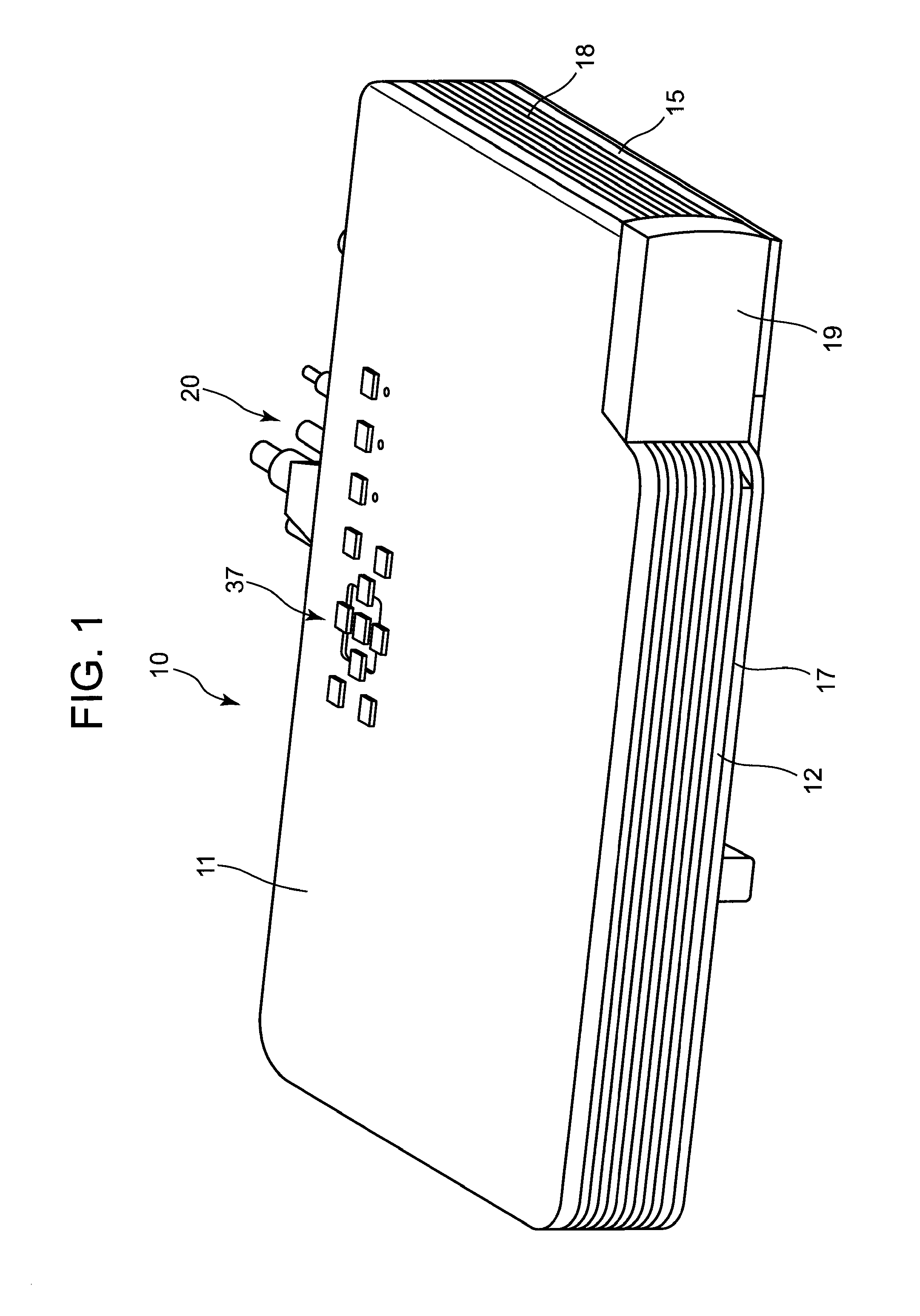
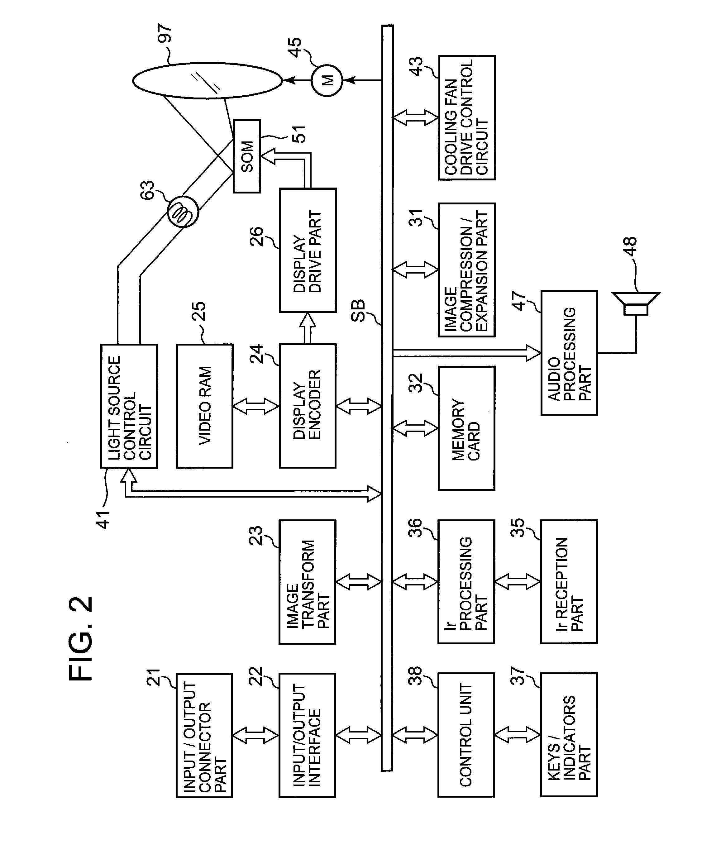
[0032]Hereinafter, an embodiment of the invention will be described. A projector 10 of the invention includes a light source unit 63, a light source side optical system 62, a light guiding device 75, a display device 51, a projection side optical system 90 and a projector control unit. The light source unit 63 is disposed so that light source light is gathered to an incident plane of the light guiding device 75.

[0033]In addition, the light source unit 63 includes an excitation light source 72 which emits light in a blue wavelength band, a fluorescent wheel 71 as a fluorescent plate, a red light emitting diod...


PUM


Abstract

With a view to providing a light source unit which can emit light source light of high luminance and high intensity even in the small quantity of excitation light, there is provided a light source unit including an excitation light source for emitting light in a blue wavelength band, a fluorescent wheel, a light emitting device for emitting light in a red wavelength band and a light guiding optical system for guiding light emitted from the fluorescent wheel and the light emitting device to a light guiding device, wherein the fluorescent wheel is made up of a fluorescent area where a green fluorescent material layer for emitting fluorescent light in a green wavelength band is disposed and a diffuse area for converting light emitted from the excitation light source into diffuse light of which directivity is weak are disposed end to end in a circumferential direction, and wherein the green fluorescent material layer is such that a concentration of weight content of the green fluorescent material in the green fluorescent material layer relative to the fluorescent material layer and a thickness thereof are determined so that a luminescent intensity of fluorescent light emitted from the green fluorescent material layer is enhanced.

Description

CROSS-REFERENCE TO RELATED APPLICATIONS[0001]This application is based upon and claims the benefit of priority under 35 USC 119 of Japanese Patent Application No. 2009-200267 filed on Aug. 31, 2009, the entire disclosure of which, including the description, claims, drawings and abstract thereof, is incorporated herein by reference.BACKGROUND OF THE INVENTION[0002]1. Field of the Invention[0003]The present invention relates to a light source unit which includes a fluorescent wheel and a projector which includes the light source unit.[0004]2. Description of the Related Art[0005]In these days, data projectors are used on many cases as image projection apparatuses which project screens and video images of personal computers and further images based on image data stored in memory cards on to a screen. These projectors are such that light emitted from a light source is concentrated to a micromirror device called DMD (Digital Micromirror Device) or a liquid crystal plate for display a colo...

Claims


Application Information

Patent Timeline
IPC IPC(8): G03B21/14F21V9/16
CPCG03B21/14G03B21/204
Inventor OGURA, NAOTSUGUOGAWA, MASAHIRONAKAMURA, HIDEKIMIYAZAKI, TAKESHIMASUDA, HIROKIKAWAKAMI, YASUYUKI
Owner CASIO COMPUTER CO LTD
Features
  • Generate Ideas
  • Intellectual Property
  • Life Sciences
  • Materials
  • Tech Scout
  • Unparalleled Data Quality
  • Higher Quality Content
  • 60% Fewer Hallucinations
Learn More