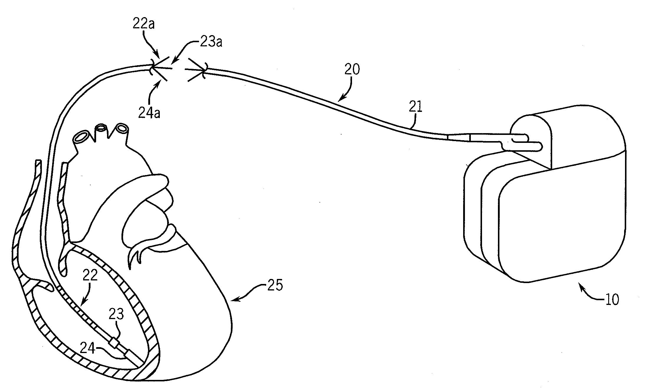
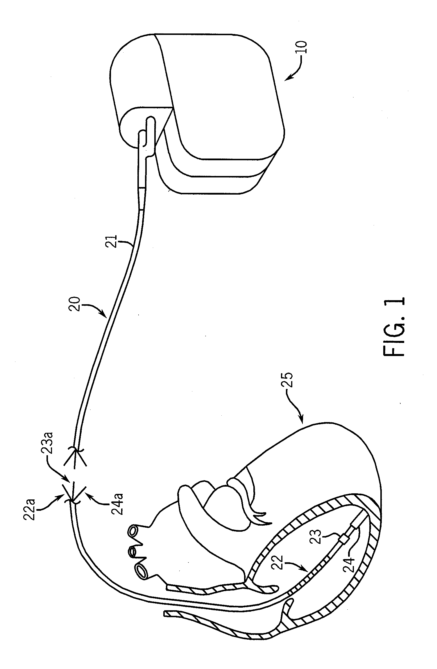
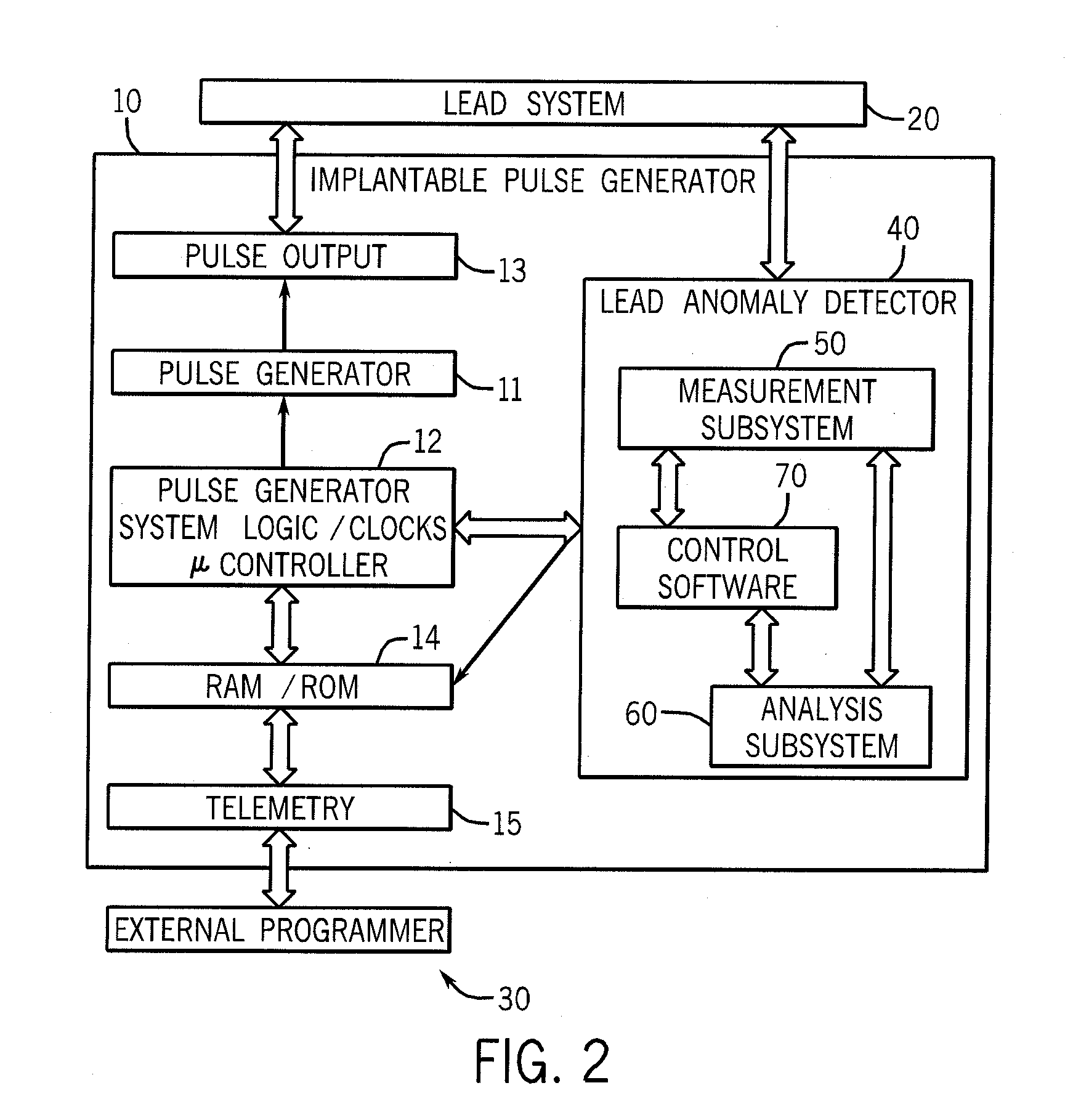
Method and apparatus for detection of lead conductor anomalies using dynamic electrical parameters

a dynamic electrical parameter and conductor technology, applied in the field of scientific and medical systems, apparatus and methods, can solve the problems of unnecessary lead replacement, corresponding expense and risk, and the existing technology for diagnosing conductor anomalies in implantable medical devices is believed to have significant limitations and shortcomings

Active Publication Date: 2011-03-03
LAMBDA NU TECH
View PDF42 Cites 38 Cited by
  • Summary
  • Abstract
  • Description
  • Claims
  • Application Information

AI Technical Summary

Benefits of technology

[0021]The present invention provides a method and apparatus for diagnosis of conductor anomalies that can be used to diagnose conductor anomalies in leads attached to an implantable medical device, such as a pacemaker, ICD, or neurostimulator. The method and apparatus of the invention are practical, reliable, accurate and efficient, and are believed to fulfill and need and to constitute an improvement over the background technology.

Problems solved by technology

Anomalies of conductors in implantable medical devices constitute a major cause of morbidity.
Functional failure of an ICD's pace-sense conductor may result in symptoms caused by loss of pacing functions for bradycardia rate support, cardiac resynchronization, or antitachycardia pacing.
A false positive confirmed clinical diagnosis results in unnecessary lead replacement, with corresponding expense and risk.
Existing technology for diagnosis of conductor anomalies in an implantable medical device is believed to have significant limitations and shortcomings.
Further, resistance measurements have limited specificity.
However, these types of “impedance monitoring,” which return values close to direct current resistance, identify lead anomalies before inappropriate shocks in only about a third of ICD patients who have conductor fractures.
Repetitive oversensing of nonphysiologically-short intervals may indicate lead conductor fracture even if lead resistance is normal.
Thus it will not detect a lead anomaly if it does not generate “noise signals” or it generates only low-amplitude noise signals, or signals that do not occur at a fast enough rate.
However, it requires sufficient oversensing to result in inappropriate detection of ventricular fibrillation clinically.
Thus it does not provide early diagnosis of conductor anomalies.
Withholding shocks for ventricular fibrillation detected on the near-field electrogram has an inherent risk of withholding life-saving therapy, however small, and is thus not the preferred approach to diagnosis of conductor fracture.
Like the Lead-Integrity Alert, it is not applicable to intraoperative diagnosis or to pacemakers and neurostimulators.
Additionally, no presently-used method reliably warns before loss of pacing function for bradycardia pacing support, antitachycardia pacing, or cardiac resynchronization pacing.
In addition to limited sensitivity, present methods for diagnosing lead conductor anomalies have limited specificity resulting in false positive diagnostics.
Evaluation of false positive diagnostics adds cost and work to medical care and may contribute to patient anxiety.
If a false-positive diagnostic is not diagnosed correctly, patients may be subject to unnecessary surgical lead replacement with its corresponding risks.

Method used


Image

  • Method and apparatus for detection of lead conductor anomalies using dynamic electrical parameters
  • Method and apparatus for detection of lead conductor anomalies using dynamic electrical parameters
  • Method and apparatus for detection of lead conductor anomalies using dynamic electrical parameters

Examples


second embodiment

[0063]the testing process is based on the effect of capacitive and inductive circuit elements on the response to a transient input (“impulse”) function. If the test signal is an impulse function, it is well known in the art that the voltage response of a series RLC circuit is given by:

v(t)=21LCexp(-R2Lt)cos{ωt+tan-1(2ωLR)}

[0064]where ω is now the natural resonance angular frequency given by:

ω=1LC-(R2L)2

As shown in the middle and lower panels of FIG. 5, the equivalent circuit has both series and parallel elements. However, these basic principles apply generally: A pure resistive circuit does not distort the input signal. Addition of a capacitive element prolongs the duration of the output signal before it reaches a predetermined fraction of the initial value. Addition of inductance results in an oscillatory response. As inductance increases, the frequency of the oscillations increases. Hence there is a decrease in the interval between baseline crossings and increase in the number of ...

third embodiment

[0066]the testing process is based on the effect of capacitive and inductive circuit elements on the response to an input signal of finite, known duration. For example, if a rectangular pulse with a fixed voltage is applied to a circuit containing only a resistor, the current in the circuit reaches its maximum value immediately. But if the circuit contains inductance and capacitance, the measured current increases gradually over time, reaching a maximum value at the end of the pulse. The time course of the current increase may be used to identify the magnitude of capacitive and inductive circuit elements. The actual measured current may be sampled frequently or continuously, or at only a few points, such as a predetermined fraction of the pulse duration and the end of the pulse.

[0067]The present method has specific advantages over methods now in use. The currently-used resistance measurement remains within the normal range if only part of the conductor is intact and is thus insensit...


PUM


Abstract

A method and apparatus to detect anomalies in the conductors of leads attached to implantable medical devices based on the dynamical electrical changes these anomalies cause. In one embodiment, impedance is measured for weak input signals of different applied frequencies, and a conductor anomaly is detected based on differences in impedance measured at different frequencies. In another embodiment, a transient input signal is applied to the conductor, and an anomaly is identified based on parameters related to the time course of the voltage or current response, which is altered by anomaly-related changes in capacitance and inductance, even if resistance is unchanged. The method may be implemented in the implantable medical device or in a programmer used for testing leads.

Description

CROSS-REFERENCE TO RELATED APPLICATIONS[0001]This application claims the benefit under 35 U.S.C. §119(e) of co-pending U.S. Provisional Patent Application Ser. No. 61 / 236,586, filed Aug. 25, 2009, which is hereby incorporated by reference.BACKGROUND OF THE INVENTION[0002]1. Field of the Invention[0003]The present invention relates, generally, to scientific and medical systems, apparatus and methods. More particularly, the invention relates to method and apparatus for diagnosis of conductor anomalies. Most particularly, the invention relates to a method and apparatus for diagnosis of conductor anomalies in an implantable medical device, such as an implantable cardioverter defibrillator (ICD), a pacemaker, or a neurostimulator.[0004]2. Background Information[0005]Anomalies of conductors in implantable medical devices constitute a major cause of morbidity. Examples of such devices include pacemakers, implantable cardioverter defibrillators (ICDs), and neurostimulators. For example, ear...

Claims


Application Information

Patent Timeline
Patent Type & Authority Applications(United States)
IPC IPC(8): A61N1/08A61N1/37A61N1/39
CPCA61N1/3706A61N2001/083A61N1/056A61N1/0504A61N1/36142A61N1/3925A61N1/08
Inventor SWERDLOW, CHARLES
Owner LAMBDA NU TECH
Why Eureka
Try Eureka