Implantable electrode assembly, implantable electrochemical power cells and implantable medical device assemblies

a technology of implantable electrodes and power cells, applied in cell components, catheters, therapy, etc., can solve the problems of limiting the performance of pacemakers, early pacemakers all suffered from leakage, and the power and energy demands of these devices are becoming increasingly difficult, so as to improve the service life of imd, reduce the frequency of battery change out and the associated surgical risks.

Inactive Publication Date: 2011-03-03
POLYPLUS BATTERY CO INC
View PDF14 Cites 9 Cited by
  • Summary
  • Abstract
  • Description
  • Claims
  • Application Information

AI Technical Summary

Benefits of technology

In one aspect the present invention provides an implantable electrochemical power cell device for providing electrical power to an implantable device, typically an implantable medical device (IMD), such as an electrical stimulator. In various embodiments the power cell device enhances IMD service lifetime, thereby mitigating the need for, or otherwise lessening the frequency of, battery change out and the associated surgical risks that go along with that. In another aspect the invention provides an implantable device system, e.g., a cardiac pacemaker system, energized by a power cell novelly configured to a pacemaker ...

Problems solved by technology

Today, as we continue to learn more about disease, new and increasingly sophisticated active IMDs are being developed, and our ability to meet the power and energy demands of these devices is becoming increasingly challenging.
For instance, the service life of the Li/I battery, the established power source of cardiac pacers for the last 30 years, is presently limiting pacemaker performance now that patient life expectancy is beyond 10 years from the date of implant.
However, those early pacemakers all suffered from leaks and short service life, the battery lasting, at best, about 2 years, and more typically less than that.
However, with increasing functionality and improve...

Method used


Image

  • Implantable electrode assembly, implantable electrochemical power cells and implantable medical device assemblies
  • Implantable electrode assembly, implantable electrochemical power cells and implantable medical device assemblies
  • Implantable electrode assembly, implantable electrochemical power cells and implantable medical device assemblies

Examples


Embodiment Construction

Reference will now be made in detail to specific embodiments of the invention. Examples of the specific embodiments are illustrated in the accompanying drawings. While the invention will be described in conjunction with these specific embodiments, it will be understood that it is not intended to limit the invention to such specific embodiments. On the contrary, it is intended to cover alternatives, modifications, and equivalents as may be included within the spirit and scope of the invention. In the following description, numerous specific details are set forth in order to provide a thorough understanding of the present invention. The present invention may be practiced without some or all of these specific details. In other instances, well known process operations have not been described in detail so as to not unnecessarily obscure the present invention.

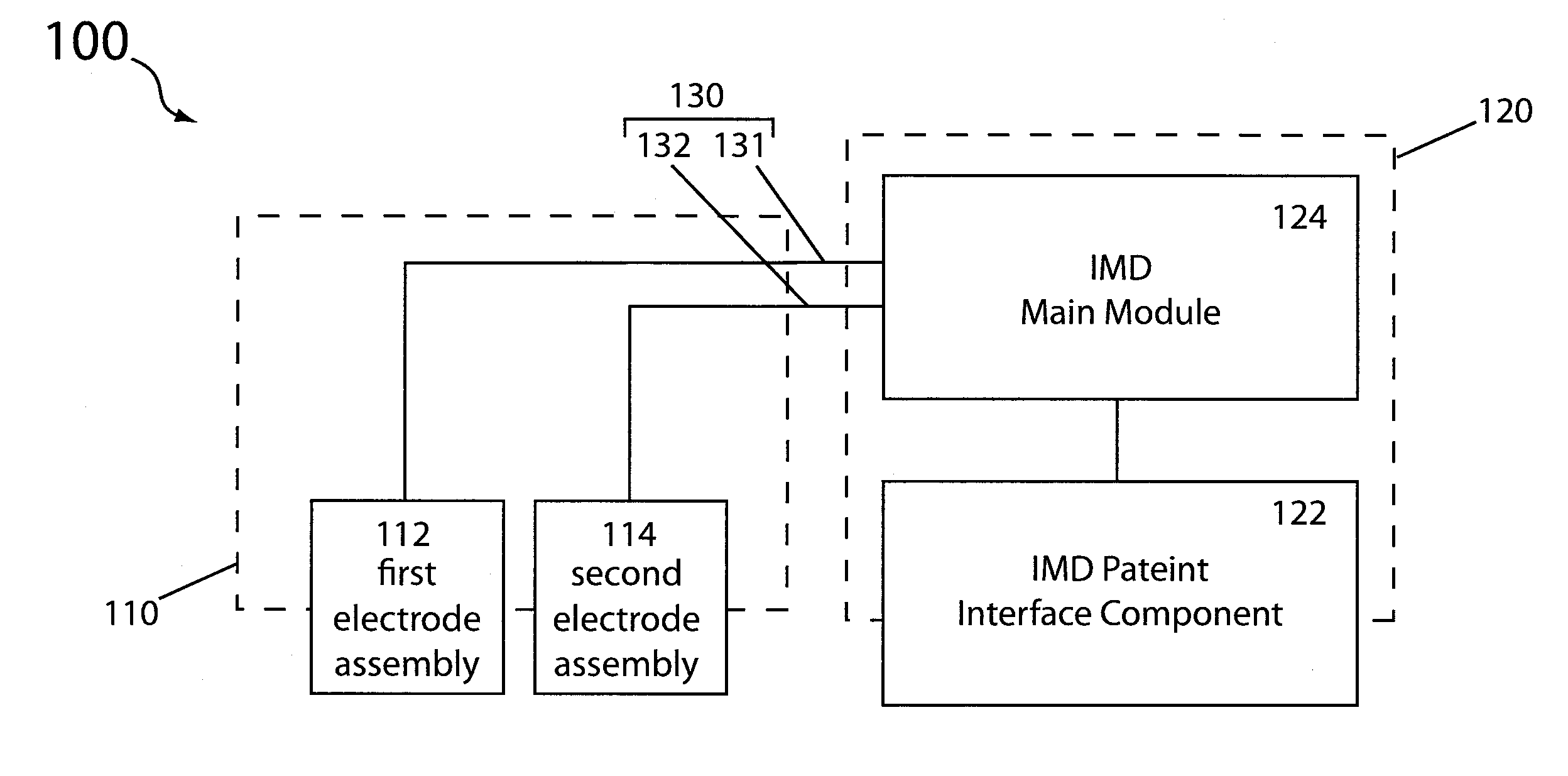
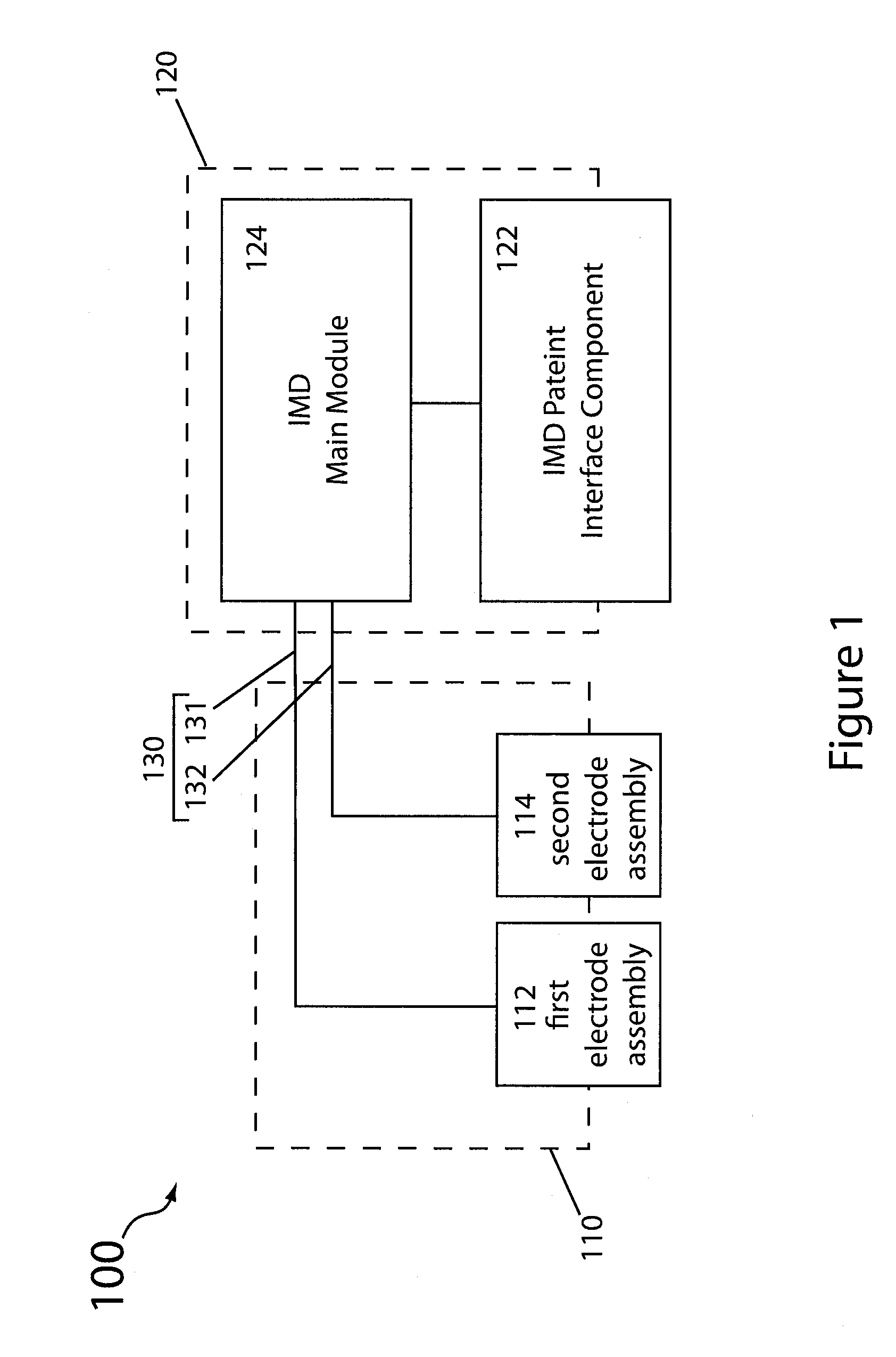
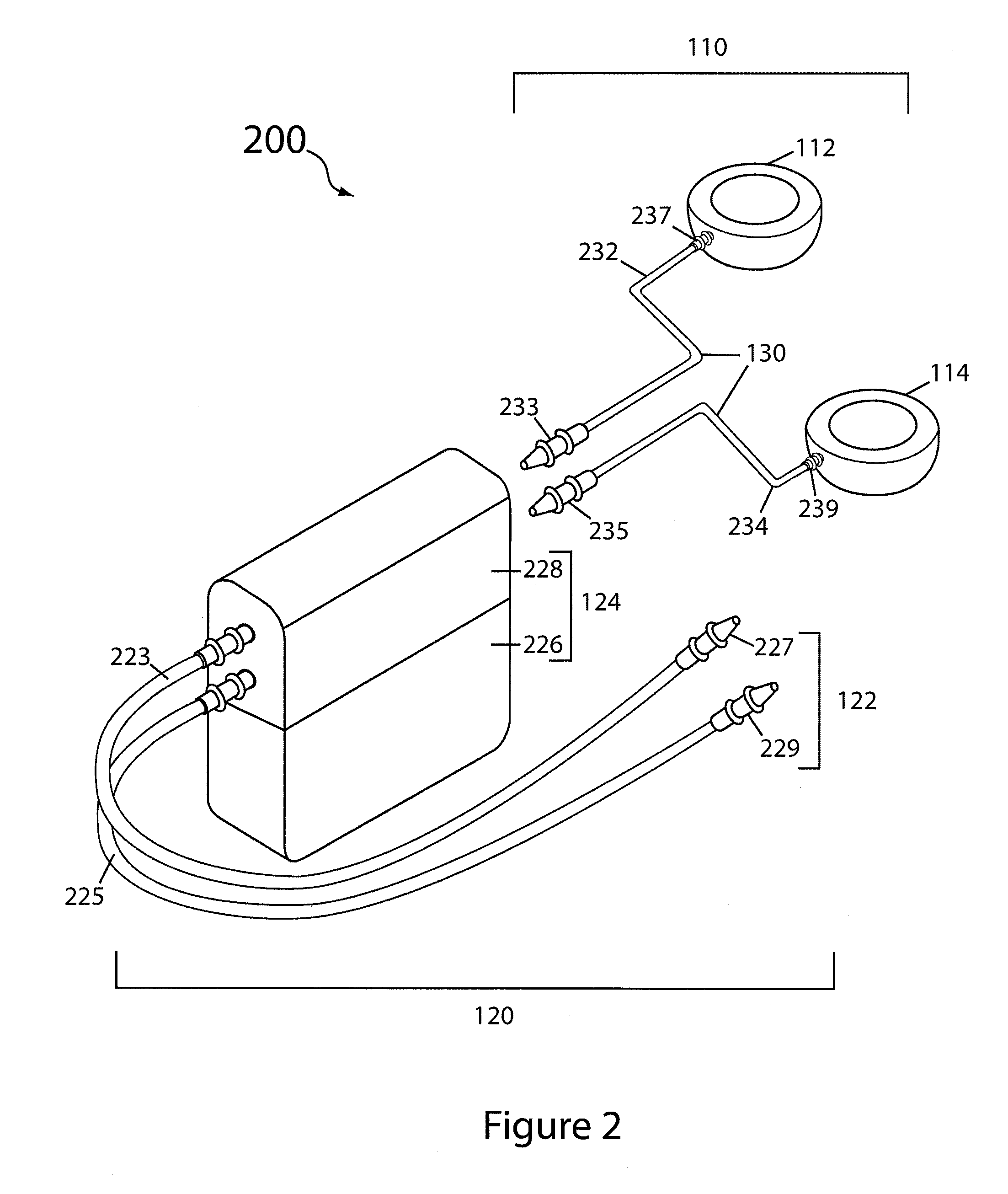
To better understand and appreciate the advantages offered by the present invention, it is first broadly described in the context o...


PUM


Abstract

Electrochemical power cells having an open-cell architecture for electrically powering an implantable medical device system include a first and a second electrode assembly, wherein at least one is a biocompatible hermetically sealed anode assembly (e.g., that of a lithium anode assembly). The power cell can be a biological lithium semi-fuel cell in which a bodily constituent partakes in the cell discharge reaction at the cathode as an active reagent. The active cathode reagent can be oxygen supplied from the body. In a particularly suitable application, the biological lithium semi-fuel cell provides electrical power to a cardiac pacemaker device, such as for a novel cardiac pacemaker system.

Description

FIELD OF THE INVENTIONThe present invention relates generally to the field of implantable devices, and in particular to devices implanted in a mammalian subject. In one aspect, the invention relates to an implantable electrochemical power cell device for the purpose of providing electrical power to an implantable medical device (IMD). In accordance with this aspect of the invention, the power cell, having what is termed herein an open architecture, includes a hermetically sealed anode assembly and a cathode assembly both of which, when in operation, contact and electrically interface with bodily fluid of the mammalian subject in which they are implanted, and bodily fluid serves as the electrolytic medium between the two assemblies. In one particular embodiment the inventive power cell device is an implantable biological lithium semi-fuel cell, wherein the anode assembly is based on electroactive lithium disposed in an hermetic housing having a lithium ion conductive wall member that...

Claims


Application Information

Patent Timeline
IPC IPC(8): A61N1/378H01M8/16
CPCA61B18/02A61B2018/0022A61B2018/0212A61B2018/0243A61B2018/0262H01M4/38H01M12/08H01M4/485H01M4/5825H01M8/16H01M10/052H01M12/04H01M4/382Y02E60/10Y02E60/50
Inventor VISCO, STEVEN J.NIMON, YEVGENIY S.KATZ, BRUCE
Owner POLYPLUS BATTERY CO INC
Why Eureka
Try Eureka