Monitoring a filter used for filtering a fluid in an aircraft engine

a technology of aircraft engine and fluid monitoring, which is applied in the direction of fluid pressure measurement, liquid/fluent solid measurement, machine/engine, etc., can solve the problems of increasing the resistance of the filter, not allowing information on the clogging level of the filter, and not allowing forecasting of the remaining life-time of the filter under actual operating conditions. , to achieve the effect of increasing the accuracy of the remaining life-time of the filter

Active Publication Date: 2011-03-03
SN DETUDE & DE CONSTR DE MOTEURS DAVIATION S N E C M A
View PDF4 Cites 47 Cited by
  • Summary
  • Abstract
  • Description
  • Claims
  • Application Information

AI Technical Summary

Benefits of technology

[0022]According to a first aspect of the invention, the set of signatures includes a time signature indicating an evaluation of the remaining operating time of said filter before reaching a predetermined pre-clogging threshold. This time signature is generated by referring to the reference clogging curve. For this, the computing means estimate the required mass from the current po

Problems solved by technology

This phenomenon, called clogging, increases the resistance of the filter to the passing of the fluid.
This first system is rather simple and inexpensive but does not allow information to be obtained on the clogging level of the filter between

Method used


Image

  • Monitoring a filter used for filtering a fluid in an aircraft engine
  • Monitoring a filter used for filtering a fluid in an aircraft engine
  • Monitoring a filter used for filtering a fluid in an aircraft engine

Examples


Embodiment Construction

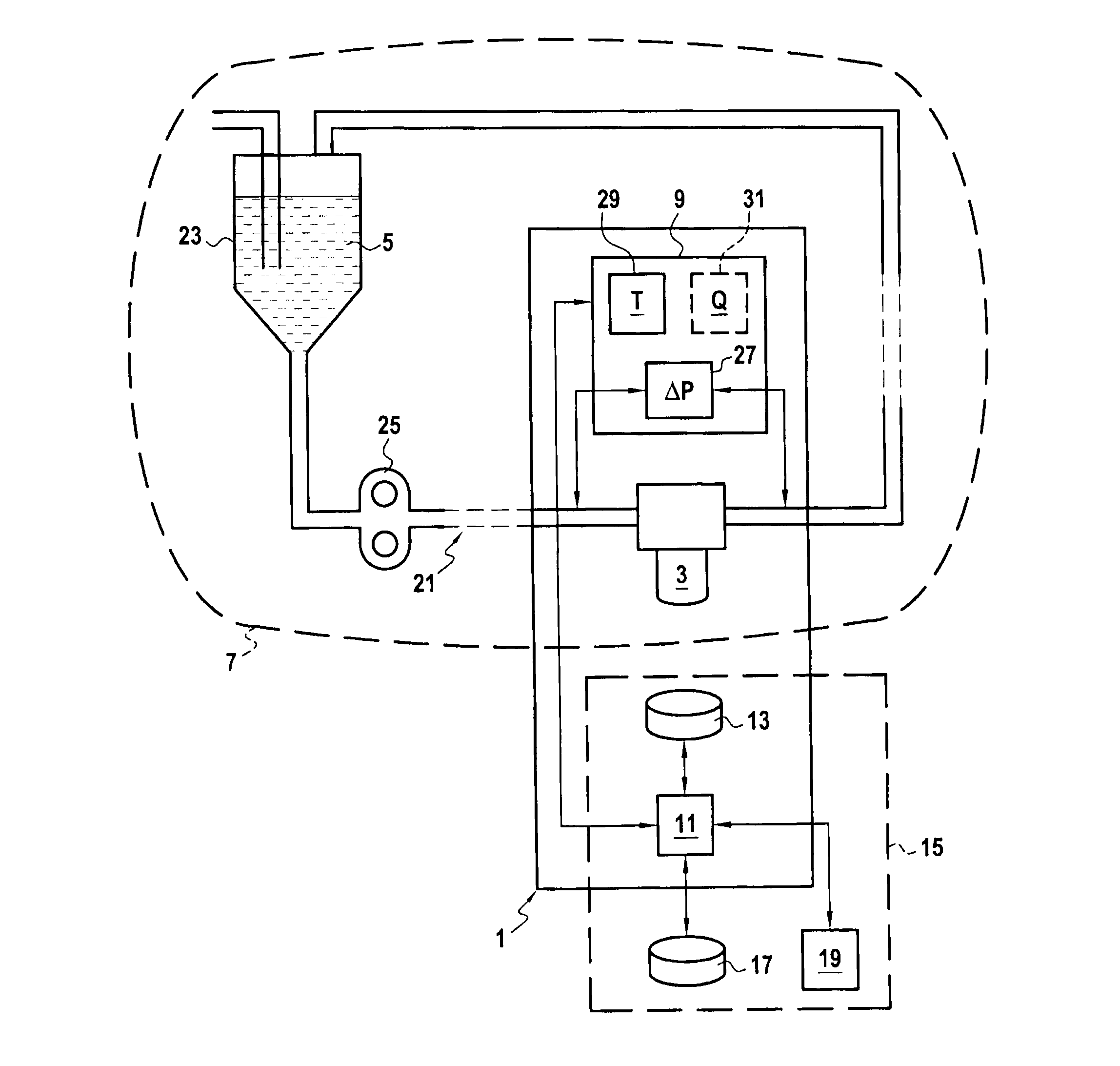
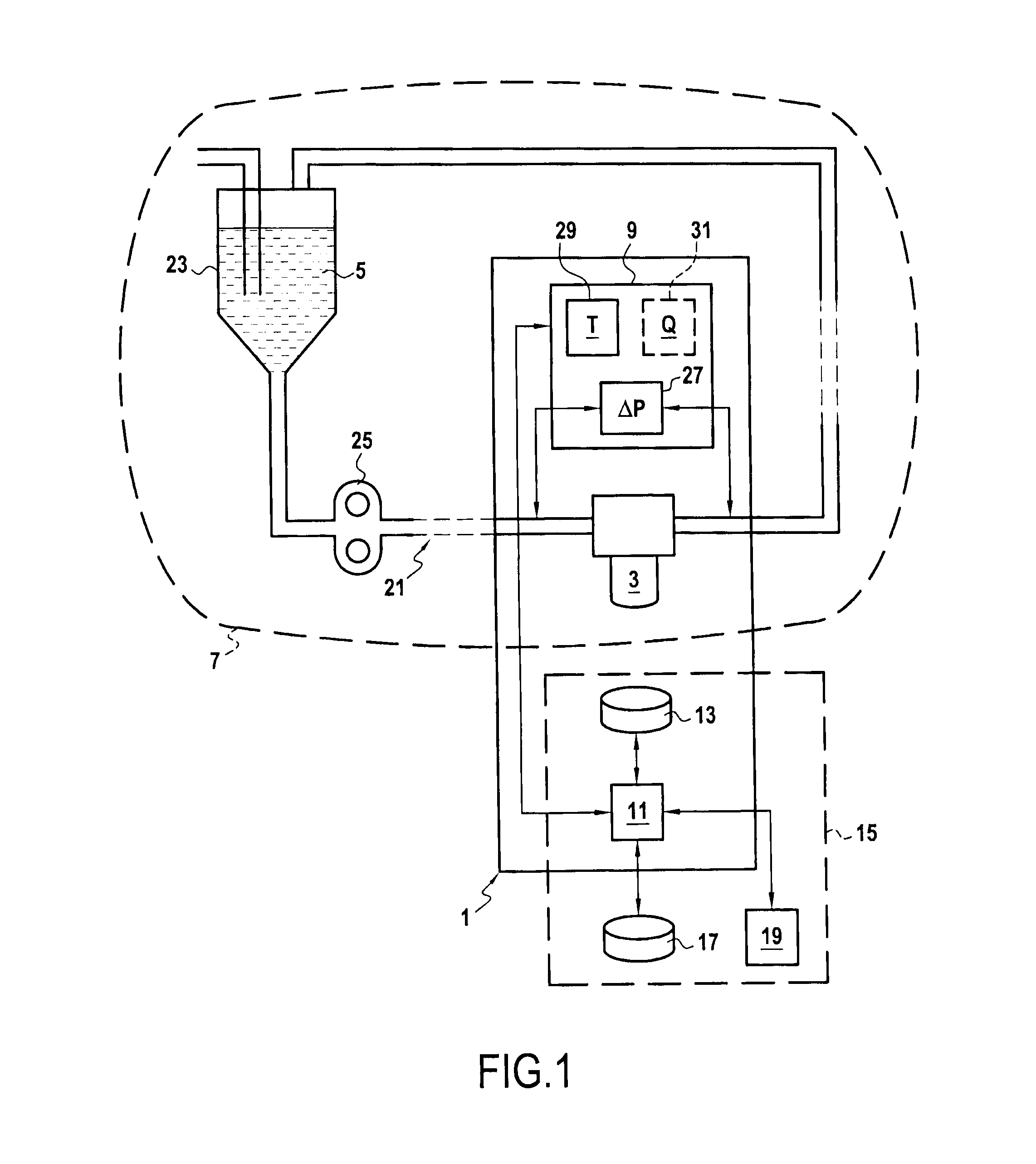
[0042]FIG. 1 illustrates a system 1 for monitoring a filter 3 used for filtering a fluid 5 (oil or fuel) in an aircraft engine 7 according to the invention.

[0043]Monitoring the physical condition of the filter 3 is carried out all along its life-time and does not consist in detecting a failure a posteriori, but in preventing these failures in a perspective of optimizing maintenance costs.

[0044]The key aspects of the monitoring system 1 consist of identifying the clogging level of the filter 3, of anticipating the wear of the filter 3 during normal or abnormal use in order to predict the remaining life-time before reaching the pre-clogging threshold of the filter. The goals of the monitoring of the main oil and fuel circuit filters are monitoring the clogging of the filter with the purpose of ensuring that it operates properly, for example for the next 20 flights. Moreover, detecting an operating abnormality of the oil / fuel systems or of the filter or detecting abnormal pollution, is...


PUM

PropertyMeasurementUnit
Pressureaaaaaaaaaa
Concentrationaaaaaaaaaa
Depthaaaaaaaaaa

Abstract

The invention relates to a system for monitoring a filter (3) used for filtering a fluid (5) in an aircraft engine (7), including:
    • pressure measurement means (27) for acquiring over time a differential pressure of the fluid (5) through the filter (3);
    • computing means (11) for computing a normalized differential pressure under reference conditions by normalizing the measured differential pressure according to conditions for exploiting the fluid (5);
    • storage means (13) for storing in memory a predetermined reference clogging curve (Cr) describing a time-dependent change of the normalized differential pressure depending on a pollutant mass injected into the filter (3);
    • computing means (11) for estimating the pollutant mass injected into the filter (3) by projecting a current value of said normalized differential pressure onto said reference clogging curve (Cr); and
    • computing means (11) for generating from said estimated pollutant mass a set of signatures defining the condition and the time-dependent change of clogging of the filter.

Description

FIELD OF THE INVENTION[0001]The present invention relates to the field of monitoring a filter used for filtering a fluid in an aircraft engine. In particular, the invention relates to monitoring a filter installed in an oil circuit or a fuel circuit of the aircraft engine.[0002]A filter installed in a fluid circuit captures the particles present in this fluid by means of a porous material of the filtering medium. This capture causes modification of the porosity of the filtering medium which is expressed under constant operating conditions, by an increase in the differential pressure through the filter as a function of time.[0003]This phenomenon, called clogging, increases the resistance of the filter to the passing of the fluid. This may take more or less time-depending on the exposure of the filter to pollution. When the differential pressure reaches the limiting value for which the filter and the circuit have been designed, the filtering element of the filter should be replaced.[0...

Claims


Application Information

Patent Timeline
IPC IPC(8): B01D35/143B01D35/00G06F19/00
CPCB01D35/143B01D2201/54B01D37/046
Inventor CONTINI, PASCAL CHRISTOPHEFLANDROIS, XAVIERFORTE, MAXIMEHADIDA, DAVID
Owner SN DETUDE & DE CONSTR DE MOTEURS DAVIATION S N E C M A
Why Eureka
Try Eureka